dprojects / Woodworking

This is Woodworking workbench for FreeCAD
MIT License
198 stars 17 forks source link

order-of-operations based workflow #6

Closed steelman closed 1 year ago

steelman commented 2 years ago

Many thanks for this workbench. I haven't seen it in action yet, but it looks more than promising.

There is one thing, I've struggled with when designing wooden objects in FreeCAD. Oftentimes parts need to match each other rather than be of exactly specified size. Does or will your workbench enable workflow, where the right order of operations rather than very precise measurements make parts fit together? A marking gauge and a knife over calipers and a dial indicator.

Such workflow in theory should fit quite well with parametric design in FreeCAD, however, it requires some tools to indicate the order of operations and dependencies between dimensions.

dprojects commented 2 years ago

I don't know what exactly you mean. Any examples? maybe a video on youtube?

From what I understood, you would probably want to adjust the size immediately by adding another element? So far, such a thing is possible thanks to https://github.com/dprojects/Woodworking/tree/master/Docs#copy-panels It doesn't work for every case and not for any objects, of course.

If you mean that when you create objects, you would create rules in the spreadsheet right away and make the model sticky and scalable, then no. For that, you would need a reference system, each object should have its own memory and detailed information about neighbors.
steelman commented 2 years ago

If I remember correctly this is a good explanation by James Wright.

If you mean that when you create objects, you would create rules in the spreadsheet

I think the project wouldn't need to be updated. Partly because in the workflow I am trying to describe absolute values don't matter. What matters is that certain dimensions match down to 0.1 mm. But this is not achieved throgh measurement, but through fitting. A CAD program program for woodworkers* need to reflect that and show which dimensions of which elements need to fit.

And maybe this is for another issue but automatic generarion of story sticks to be made with a laser engraver would be a nice feature.

* At least for hobbyists and hand tool enthusiasts. Modern woworking producition, which involves power tools or even CNC, needs with precise dimensions and measurements and proceedes like anybother industry.

dprojects commented 2 years ago

Nice movie, I like to watch real woodworkers. I agree with the "general rule he had in mind" but he didn't say loudly and directly the most important thing:

Welcome from Poland ;-) Witam ziomek z Polski ;-)

steelman commented 2 years ago

If you deal with laminated chipboards you can't sand them, you can't sand joints to fit edges to each other. If you cut parts not precisely, you get bad looking furniture.

That is and isn't true. True, you can't sand laminated chipboards (you can, a little, if you are careful). You can, however, take a part you've already created and use it to adjust tools tools like table saw or miter saw by putting the part between the tool's blade and a fence. It's even better if you first set up a tool (with a laser engraved story stick) and then cut all the pieces without moving the tool. To do that you need to know which dimensions of which parts are the same dimension. That is my point: mark corresponding dimensions of different parts (e.g. width of all four boards making up a drawer and lengths of opposite pairs) somehow and use that information to build a cut list. But not a regular one where you've got exact dimensions grouped by parts (board #1, 18x100x500 mm; board #5, 18x100x250 mm; board #21, 18x100x350 mm) but rather grouped by corresponding (matching) dimension: dimension A — 100 mm±5mm, parts: #1, #5, #21. Which means: dimension A of parts #1, #5 and #21 may be somewhere between 95 and 105 mm but it must be the very same on all three parts.

👋 (-;

dprojects commented 2 years ago

Only that the computer is not a carpenter and does not know which elements can be "arbitrary" and which must be "predetermined". You can tell it by Spreadsheet making the important measurements parametric. You can see here: https://github.com/dprojects/Woodworking/tree/master/Examples/Parametric

I have no experience with other 3D CAD systems, but I suspect that no program on the market is able to guess which parameters are to be constant and which ones are optional. You can use constraints for that at FreeCAD.

For it to work like this, it would probably require some expert learning systems based on artificial intelligence and knowledge in the field of carpentry. FreeCAD is not so stable software as to build such complex and advanced systems on it. It would already be better to write FreeCAD from scratch with just a few features. Then it would be possible to develop such a project without worrying about "not needed changes" and "lack of stability" at FreeCAD.

A report with dimensions could probably be partially achieved by adding a special one in the BOM tool: https://github.com/dprojects/getDimensions/tree/master/Docs#report-types

However, the basic difficulty is to understand how this should work. I am not sure if the order-of-operations is the thing. PartDesign has order of operations, you build one on another but it not means the box at the top is defined by those ones below.

steelman commented 2 years ago

Dnia 31 sierpnia 2022 18:25:07 UTC, Darek L @.***> napisał/a:

Only that the computer is not a carpenter and does not know which elements can be "arbitrary" and which must be "predetermined".

But I as a designer know.it.

For it to work like this, it would probably require some expert learning systems based on artificial intelligence

As far as I am concerned, I am totally fine if I can add all these information by hand as a part of design process (think about it as a production engineering) and have it available:

-- Łukasz Stelmach z podróży

dprojects commented 2 years ago

I am totally fine if I can add all these information by hand as a part of design process

You can use Sketch constraints for defined dimensions and leave other not measured. And you can generate report for named constraints only: https://github.com/dprojects/getDimensions/tree/master/Docs#a---report-type

to highlight elements that need to match

This is interesting but it needs more description. For example if you have 4 legs of the table you can bind them by making Array, or Link all the 3 legs to the first one. Also you can bind all legs with Spreadsheet. Also you can use MultiTransform Mirror to get all legs from single one.

to build dimension oriented cut list

You can manually group things with https://github.com/dprojects/getDimensions/tree/master/Docs#g---report-type For example you can make folder "A — 100 mm±5mm" and put there what you want. All the objects will be calculated as group.

to engrave a story stick with a laser (it may not be practical, but I think it is a cool idea)

I am not familiar with "engrave a story stick with a laser", I don't know what it is. Some kind of note at the wood?

steelman commented 1 year ago

You can use Sketch […]

This is good. The deficiency I can see, is that you don't make everything with sketches. Sometimes you extrude them and need to bind the extrusion length to something different.

This is interesting but it needs more description. […]

OK, I can see a general answer which does not surprise me much, that there are means to preserve and present information I want. However, what all these methods lack IMHO is generality. You want to be able to bind in any two or more dimensions and have (on demand) clear visual indication of this relationship.

For example, imagine a shaker style leg that is 65 cm long. The top 10 cm are straight with a 6.5x6.5 cm square cross section and below it is tapered down to 3x3 cm at its bottom. You want to bind this 10 cm dimension to width of stretchers that connect the legs below the table top. Then in the shop you begin by making the stretchers and it doesn't matter if you make them 98 mm or 103 mm. The plans say: take a stretcher and mark its width on the legs (it may also say, and leave ~3 mm at the top, so you can later cut it flush). So the graph you build by binding dimensions of different objects together is directed and describes order of operations. It's not only about equality of dimensions but rather their implications.

Spreadsheet may be a good place to start (and I use it) but a the moment it does not provide means to visually identify objects using the same cell as one their dimensions, neither it is possible to visualise dependencies (implications) between dimensions (think spreadsheets highlighting cells referred in a formula).

For example you can make folder […]

Sounds close, but I need to see it in action.

I am not familiar with "engrave a story stick with a laser", I don't know what it is. Some kind of note at the wood?

Yes, with interesting properties. Story sticks were ancestors of gauge blocks. Such stick was not a stick at all but rather a nice straight piece of wood with marks on it made with a knife. Such marks make precise reproduction of sizes easy. You put a stick next your work piece, put a knife in a mark on the stick and leave a mark on your work piece. Knife marks are very precise because the have no width (they have, but it is a part of the waste). Manually made sticks provided precision (all pieces of furniture made with one particular stick were the same size) but not accuracy (each stick was different, unless copied from another stick, then it was only tiny bit different). Laser made story sticks can be both precise (you physically transfer from one object to another by holding a knife against the template) and accurate (repeatable).

dprojects commented 1 year ago

For example, imagine a shaker style leg that is 65 cm long. The top 10 cm are straight with a 6.5x6.5 cm square cross section and below it is tapered down to 3x3 cm at its bottom. You want to bind this 10 cm dimension to width of stretchers that connect the legs below the table top. Then in the shop you begin by making the stretchers and it doesn't matter if you make them 98 mm or 103 mm.

You can do it with Sketch. Set constraints only for the 10 cm and leave the Sketch not fully constrained until the moment you know the measure at the end of modeling.

clear visual indication of this relationship.

I have no idea what you mean by that.

The plans say: take a stretcher and mark its width on the legs (it may also say, and leave ~3 mm at the top, so you can later cut it flush).

But at FreeCAD you can edit the Sketch, and add exact constraints later.

visualise dependencies (implications) between dimensions (think spreadsheets highlighting cells referred in a formula).

There are not dependencies between dimensions. However, the "spreadsheets highlighting" sounds good to me. I think such feature will be useful.

Yes, with interesting properties. Story sticks were ancestors of gauge blocks.

In Poland we call it "traser stolarski", albo "znacznik stolarski" ;-)

But I think I know where is the problem. The problem is not strictly in order-of-operations. It is in planning project. Carpenters of raw wood, the real woodworkers, in general don't plan. They have piece piece of paper and pencil. They have no idea how it is possible to plan all dimensions. This mostly because raw wood is natural product that works, so the dimensions are not sure. So they cut, they sand until they get smooth surface and joints. But the dimensions are the result of the process somewhere +/- around the plans. The CNC a little changed this process.

This is why they are not able to accept the dimensions-oriented planning.

However, winter is coming. So, I will keep this issue open, because I think this topic is interesting and worth to improve somehow. It is hard because it is not possible to change so drastically the FreeCAD designing process. But I think "some tools" may help to deal with planning and designing.

For example:

steelman commented 1 year ago

Yes, with interesting properties. Story sticks were ancestors of gauge blocks.

In Poland we call it "traser stolarski", albo "znacznik stolarski" ;-)

Oh, I love discovering traditional Polish names for tools I learn about on YT. Nope, „znacznik stolarski” is a „marking gauge” and „gauge blocks” are „płytki wzorcowe” (-; And story sticks can have several cuts marking different lengths.

Carpenters of raw wood, the real woodworkers, in general don't plan.

Of course they do. They plan the order of operations. They simply need only high precision without high accuracy. It's neither good nor bad, that is their project requirement.

This is why they are not able to accept the dimensions-oriented planning.

No, it is for completely different reason: they don't need to, to make one off projects in their own shop. Dimensions expressed precisely in universal units enable industrial production but bring little advantage to a small artisan shop. They require sophisticated measuring tools (callipers at least, probably a dial indicator, tape measure is definitely not enough) and inconvenient procedures to achieve required precision, which in such a shop can be (and has been for centuries) achieved by much simpler means.

Take for example the kerf maker tool used to adjust table saws: no units, no measurements, high precision. Or the Iskra drill. Yes, parts of the set are calibrated in mm to enable working with parts made in factories, but the idea to avoid measurements is in the very core of its design.

Thank you very much, for exhaustive and insightful answers.

PS. [Precision vs accuracy].(https://en.wikipedia.org/wiki/Accuracy_and_precision)

dprojects commented 1 year ago

https://www.youtube.com/watch?v=EP6tz6AelH4 used to adjust table saws: no units, no measurements, high precision.

Rather zero precision, because after measuring he moved this piece of wood manually, without any support. He did it fairly precisely because he was skilled to do so. But everyone know this channel, it was about advertising. I used to watch this homie but he went too much on advertising. However, I appreciate his work.

https://www.youtube.com/watch?v=HizVveBMzco)

You can always have a 30 kg template at hand ;-) But it's nice that such products are created in Poland and are promoted. There are always problems with perpendicular drilling. I personally use Wolfcraft Doweling Jig for pilot holes: https://www.wolfcraft.com/products/wolfcraft/en/eur/products/attachments-for-machines/drill-guids/dowelling-p/p/p_4650

Woodworking workbench supports doweling and drilling with 32 mm offset: Doweling: https://github.com/dprojects/Woodworking/tree/master/Docs#magicdowels Drilling: https://github.com/dprojects/Woodworking/tree/master/Docs#magicdriller

I like to watch creative woodworkers. Real carpenters create their own tools, the most accurate and practical

I always admire the ingenuity of such people: https://www.youtube.com/c/G%C3%B6kmenALTUNTA%C5%9E/videos https://www.youtube.com/c/Celal%C3%9CnalCelalunal/videos

I like also to watch this woodworker from Poland, he use machines and make really nice furniture: https://www.youtube.com/c/MebleTwojegoPomys%C5%82u/videos

dprojects commented 1 year ago

(think spreadsheets highlighting cells referred in a formula).

img

dprojects commented 1 year ago

Yesterday I added new feature named: showConstraints and it selects all edges with the same constraints. It can be used for quick preview if the edge is measured and can't be changed or there is no selection at the edge so you may be able to change it via Sketch. I think this feature might be useful.

At the gif below all elements are fully constrained except the one. So there is only vertical edges selection. There is no horizontal constraint. Also this show "order-of-operation" approach. How you can postpone the measurement. If you don't know exact dimension you can leave it not measured.

img

dprojects commented 1 year ago

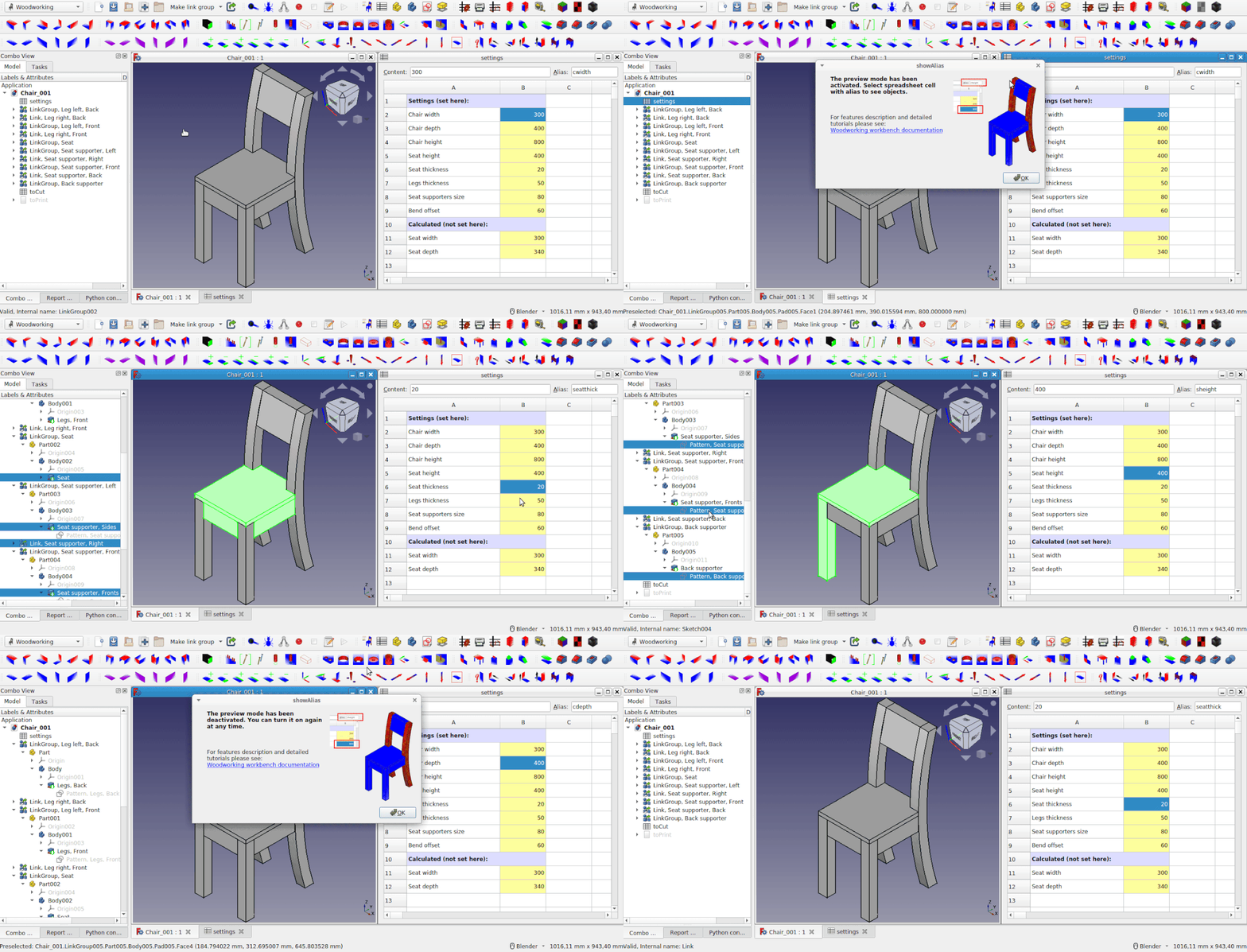
There is also some kind of raw wood tutorial where is described how to approach order-of-operations by glued table top example. Maybe this is not perfect according to all grain direction rules but it shows the approach.

For me such designing is some kind of "over-designing", you can just create table top and usually carpenters know how to deal with grain direction to create table top. What kind of operations they need to do step by step. But if you want to simulate the process you can do it ;-)

steelman commented 1 year ago

I am not sure the term raw wood is accurate. I haven't seen it before. I believe solid wood (as oposed to all types of engineered wood) is the right one.

PS. Carpenter is cieśla and they don't mind being off by a centimeter (-;

dprojects commented 1 year ago

I am not sure the term raw wood is accurate. I haven't seen it before. I believe solid wood (as oposed to all types of engineered wood) is the right one.

PS. Carpenter is cieśla and they don't mind being off by a centimeter (-;

I am not sure if this is accurate too ;-) "raw wood" it is just my quick invention "surowe drewno", for me it means, almost like tree, not covered by oil, wax, veneer or not prefabricated like plywood. Plywood is also real wood but is created, manufactured. Raw wood is more like fresh tree cut. I came across name used often "timber" but in Poland is "tarcica" "lumber"?

steelman commented 1 year ago

Raw may (in English) suggest that it is green (wet, just fallen, not dried), and green woodworking has been a thing for the past couple of years (watch Peter Follansbee's videos).

Timber and lumber mean the same, each on its side of the pond and probably with their definition

wood that has been cut into various lengths for building

are IMHO what you mean.

There is a term rough sawn (lumber/timber/wood) which is the term closest to tarcica as far as I can tell.

dprojects commented 1 year ago

watch Peter Follansbee's videos

I subscribed him and watch it someday for sure. I like his style, it makes me smile, this beard and primitive tools, he looks like a real carpenter from a bygone era ;-)

Raw

Is taken from computers file formats, raw file format means not post-processed, as it is. But also it is direct translation from google ;-) raw wood, lumber

There is a term rough sawn (lumber/timber/wood) which is the term closest to tarcica as far as I can tell.

Real carpenters buy wood at a sawmill and not some plywood like me in Castorama ;-) I am not carpenter, my grandfather was, I have his ancient thickness planer from wood and hand-saw, so I only heard the terms "wood", everything is wood ;-) For me panels are usually at the floor but people at FreeCAD forum use panels terms all the time in relation to wood. They use term timber mostly for real wood construction elements.

There is also Moon Wood ;-) some kind of best quality wood ;-)

Maybe I will update the header with "raw wood, rough sawn, timber, lumber" ? I am not sure if the term "rough sawn" will be clear for people outside carpentry. This is the first time I hear such a term. So I think this should be "carpentry professional term" + "normal user term". So this should be also clear for people without carpentry knowledge.

dprojects commented 1 year ago

I added YouTube channel. So, I will be able to post new features and tutorials without overloading the github. There is also glued table top movie which shows step by step how to force the order of operations.

I will close this issue because I don't see anything that should be done more. Feel, free to open "feature request" issue here.