prusa3d / Prusa-Firmware-Buddy

Firmware for the Original Prusa MINI, Original Prusa MK4 and the Original Prusa XL 3D printers by Prusa Research.
Other
1.17k stars 229 forks source link

[ENHANCEMENT] MK4 and XL Power Panic Bypass (for use with UPS systems) #3255

Closed IBNobody closed 5 months ago

IBNobody commented 1 year ago

Enter what type of printer or upgrade the enhancement applies to. Printer type - MK4, XL Optional upgrades - None

Is your suggested improvement related to an existing problem? Please describe.

The current buddy firmware checks the state of the power panic line during initialization and throws error 13321/ ERR_ELECTRO_ACF_AT_INIT if the power panic line is disconnected. There is no way to bypass this in the firmware.

https://github.com/prusa3d/Prusa-Firmware-Buddy/blob/56a40a0f776bb096468b47f52eb158e0afc84e08/src/common/power_panic.cpp#L62C1-L62C1

In this code, the acFault line is polled and checked to see if it is LO. If it is LO, Error 13321 / ERR_ELECTRO_ACF_AT_INIT is thrown.

This is fine for normal users, but if you have a UPS battery backup, power panic falsely trips when the PSU is switched over to battery backup. On the MK3, the common solution would be to disconnect the power panic wire from the PSU to the Einsy. However, on the MK4, disconnecting the power panic wire causes the printer to throw error 13321 on boot.

(I theorize that the xbuddy PCB omitted a pull-up resistor that was present on the Einsy.)

Describe the expected functionality

Ideally, Error 13321 / ERR_ELECTRO_ACF_AT_INIT would not be thrown on boot. It should be thrown when attempting to print and should not gate adjusting any settings on the MK4.

The check for the acFault should also be bypassable via a firmware setting allowing us to disable power panic.

m-cas commented 1 year ago

Silly question: usually IO pins on modern hw have the capability of having pull-up resistors embedded and switched on/off via sw. Did you explore if the "missing pull-up" could be set upon startup to avoid 13321 on boot? I am unfamiliar with this specific HW but I spent a decade programming similar items...

IBNobody commented 1 year ago

Silly question: usually IO pins on modern hw have the capability of having pull-up resistors embedded and switched on/off via sw. Did you explore if the "missing pull-up" could be set upon startup to avoid 13321 on boot? I am unfamiliar with this specific HW but I spent a decade programming similar items...

Good catch. I had just assumed it was intended to be pulled up with a physical resistor.

https://github.com/prusa3d/Prusa-Firmware-Buddy/blob/56a40a0f776bb096468b47f52eb158e0afc84e08/src/common/hwio_pindef.h#L348C1-L348C234

MACRO_FUNCTION(buddy::hw::InterruptPin, acFault, buddy::hw::IoPort::G COMMA buddy::hw::IoPin::p0, IMode::IT_falling COMMA Pull::none COMMA configLIBRARY_MAX_SYSCALL_INTERRUPT_PRIORITY COMMA 0, power_panic::ac_fault_isr) \

I believe Pull::none needs to be Pull:up.

m-cas commented 1 year ago

It should be a rather easy test: pull::up, disconnect the cable, boot :) easiest test ever!Let me know if it works!Btw, I agree this should be a config option!

IBNobody commented 1 year ago

@m-cas

Not necessarily easy for us to test - we have to break a tab off the xbuddy in order to flash unsigned code. See the schematics for the mini's buddy to see what I mean. Not ready to commit to this just yet.

m-cas commented 1 year ago

You are right!!Ok, than let’s hope for this to make it into a configurable option… it should be so to prevent a perfectly good printer to stop working in case the little cable gets damaged until said cable is replaced. 

tkircher commented 1 year ago

Thanks for opening this. I intend to run my MK4 off isolated 24V DC generated from a battery, so the Delta PSU would not be plugged in at all, and would just remain in place for mechanical purposes. It would really be nice to just turn off the power panic option entirely for this.

m-cas commented 1 year ago

I guess that if one would like to have that capability right now, one could disconnect the cable from the psu and connect said cable up to whatever vref it needs (hw schemata would need to be checked) with a big resistor achieving the needed ‘pull up’ (see https://learn.sparkfun.com/tutorials/pull-up-resistors/all if needed). Good to go without touching the board or waiting until prusa decides if to implement this request in firmware.

tkircher commented 1 year ago

I guess that if one would like to have that capability right now, one could disconnect the cable from the psu and connect said cable up to whatever vref it needs (hw schemata would need to be checked)

There isn't a schematic available for the MK4 Buddy board. It isn't clear whether the signal is a voltage from the PSU, a circuit closed by the PSU, an active signal between the two, or what. Maybe it isn't just an I/O line pulled up to vcc, or pulled down to ground. Who knows.

m-cas commented 1 year ago

I have not the time to go search in the firmware but I strongly suspect it is an interrupt routine triggered by a H to L change (or viceversa). When the psu looses the main the line changes value signaling that you have only the few fractions of seconds to save infos until the capacitors are empty. It it were a pull-down simply grounding the line w/ a big resistor would do the trick (and easy to test) But w/o hw we still do not know the vref for a pull-up if that’s how it is implemented.Step 1 woukd be to find the code where the interrupt is setup to see to what signal change it will react to…

m-cas commented 1 year ago

I did finally check the code. On boot the code checks if the line is "low", if this is the case it throws an error. During the runtime an interruption routine catches the signal falling down and triggers the printer to gracefully stop the work. So the solutions are:

m-cas commented 1 year ago

I did found the hw diagrams for the PSU: https://github.com/prusa3d/MK3_Power_Panic/blob/master/rev._Delta_PMZ-24V240WDAL/Delta_PMZ-24V240WDAL.pdf

tkircher commented 1 year ago

I did found the hw diagrams for the PSU: https://github.com/prusa3d/MK3_Power_Panic/blob/master/rev._Delta_PMZ-24V240WDAL/Delta_PMZ-24V240WDAL.pdf

According to the diagram, you should be able to use a 10k ohm resistor to connect the cable to 24vcc and "trick" the system into believing that the PSU is healthy. No guarantees, please check the diagram yourself before doing anything.

DO NOT connect anything to 24v. The 2N7002 is an N-channel MOSFET, it would be pulled up on the xBuddy board itself, and switch between the ARM chip's V_IO/Vcc and ground depending on how the gate is driven.

The optoisolator would be active when AC is on, driving the gate high on Q170, driving the gate low on Q171. When Q170 goes low in a power failure, R173 would pull the gate up on Q171 turning it on and pulling pin 1 on CN2 to ground and signaling a fault.

The question is why it would throw a fault with the cable not connected, if it's pulled up on the xBuddy board. If there is no circuit to change the pin state during a failure it should just continue to think there isn't a problem. But clearly it can't just be run without the cable connected so something else is going on that we can't see without the xBuddy schematic.

m-cas commented 1 year ago

At the end, it is as I was saying before: the pin goes down when the line input to the psu stops.

You do not need the buddy schematics: if you look at the code you will see that the firmware doesn’t initialize the buddy board port to be pulled-up. That is the change this request is all about. The HW pull-it-yourself-up is a possible TEMPORARY measure until the FW is changed.

To recompile the FW would work fine but it would mean forfeiting the warranty by breaking a bridge to allow non-signed firmware on the board.

IBNobody commented 1 year ago

@tkircher Thanks. Beat me to it. I agree. Don't pull anything up to 24V. Before anyone does anything, get a DMM out and measure.

@m-cas Thanks for finding me the Delta PSU schematic. This helps. It looks like the MK3 with the old PSU had an external PCB, and the new Delta Black PSU integrated the schematic you linked.

The question is why it would throw a fault with the cable not connected, if it's pulled up on the xBuddy board. If there is no circuit to change the pin state during a failure it should just continue to think there isn't a problem. But clearly it can't just be run without the cable connected so something else is going on that we can't see without the xBuddy schematic.

I was initially leaning towards the "they did not populate the pull-up" resistor, but now I am not so certain. The Delta PSU Power Panic circuit is open-drain and will not function without a pull-up.

Without an xBuddy of my own (order still "two weeks out"), I am only able to be an armchair EE. You can bet that as soon as I get my hands on the PCBA, I'm going to beep it out.

Here's the PCBA.

xBuddyboardnocables-1

At first glance, I don't see a missing resistor other than the one next to the slot tied to PE Ground.

For reference, here is the Einsy Rambo MK3S+'s power panic circuit.

image

EDIT:

The HW pull-it-yourself-up is a possible TEMPORARY measure until the FW is changed.

Agreed. (Though without any comments from the FW maintainers, this is all we have without pulling up that appendix.)

m-cas commented 1 year ago

There is no need for a physical resistor on the board, it is something that can be setup in sw.

IBNobody commented 1 year ago

If you look at the psu scheme, you should see that there is a 10k resistor doing the pullup, that is why -I guess- it wasn’t done in the sw.There is no need for a physical resistor on the board, it is something that can be setup in sw

Yeah, but if there was a physical pull-up, then why is disconnecting the cable causing it to read acFault as Lo?

Let me see if I can drum up some support on Reddit.

m-cas commented 1 year ago

If you disconnect the cable from the psu the buddy port reads a low value (I guess it defaults to pull-down) thus triggering a fault.

tkircher commented 1 year ago

Because the pullup is inside the psu. If you disconnect the cable from the psu there is no pullup anymore and the buddy port reads a low value (I guess it defaults to pull-down) thus triggering a fault.

There clearly isn't a pull-up in the schematic you linked. You yourself also pointed out that the acFault pin (PG0, pin 56 on the xBuddy's STM32F427) is set to Pull::none. (Just for reference, according to the datasheet this pin is 5v tolerant.)

jseyfert3 commented 1 year ago

Here from Reddit. I've got a scope in my car, but I'm not home tonight. If someone doesn't do it first, and someone can help remind me to do it, I'll try to scope out the power panic on my MK4 tomorrow evening and see what's happening.

IBNobody commented 1 year ago

Here from Reddit. I've got a scope in my car, but I'm not home tonight. If someone doesn't do it first, and someone can help remind me to do it, I'll try to scope out the power panic on my MK4 tomorrow evening and see what's happening.

If you do not get to it, I will be able to investigate shortly. My printer will arrive Tuesday.

jseyfert3 commented 1 year ago

I started looking at this this morning. There are 2 volts across the power panic terminals IF the power panic cable is plugged in and the printer is powered on. If the power panic cable is disconnected, there is no voltage across the power panic terminals. This makes sense, since as pointed out the PSU power panic terminals are open drain, so it cannot generate any voltage.

There is a lot of noise when the supply is running. I ended up doing a differential measurement on the scope to eliminate the large amounts of common mode noise. You could see the noise between ground and the negative terminal of the power supply. I could not ground the probe at the negative of the power supply due to this noise because the scope, while USB, is connected to my desktop PC so it is grounded.

The following image is the point at which I flipped off the power supply using the switch on the supply, with the power panic cable connected. Channel A (blue) is connected to V+ and channel B (red) V- on the power panic terminals. Ground leads were clipped together and not to anything else since I was doing a differential measurement. I added a math channel of A - B (purple), which shows the two volts across the power panic terminals when the printer is on and power panic cable is connected. image IMG_2789

If we zoom in on the differential channel, there's a slight 60 Hz oscillation in the voltage. image

I'm unclear if the differential voltage oscillation is an artifact of the differential measurement, or if that's important. I saw something similar when I tried probing the power panic cable with the cable disconnected from the PSU and the printer was on.

I also noted there's a 100 nF cap on terminal 1 in the Delta PSU schematic linked above. I wonder if that capacitor is how the buddy board knows if the cable has been disconnected from the PSU. You could have an internal pull-up on the xBuddy, then quickly turn that off, pull the IO low really fast and check the voltage, then go back to a normal input with pullup. This similar to what I've read about for making DIY capacitive touch buttons for Arduino projects.

I'd love to poke at this more but I need to get to work unfortunately. Let me know what else you want me to try. Not sure I want to remove my xBuddy board from the box but I can certainly remove the cover and poke at it a bit.

20230925-0003 switch off, single waveform.psdata.zip

m-cas commented 1 year ago

@tkircher Thomas, you are right, there is no pullup inside the psu. I shouldn't read schematics when I don't have enough time for that. This said, only two possible way to solve this:

Do you see any other solution?

IBNobody commented 1 year ago

@Crusher7485 Thanks. This is really good. I have my MK4 being delivered soon and will be able to look directly at the xBuddy board. I plan on powering up the board and seeing what it is doing.

There are 2 volts across the power panic terminals IF the power panic cable is plugged in and the printer is powered on.

This is helpful. I would have expected the voltage to be higher. One thing that was not clear: If you unplug the power panic cable from the PSU and measure the voltage across the terminals, is it still 2V?

If the power panic cable is disconnected, there is no voltage across the power panic terminals. This makes sense, since as pointed out the PSU power panic terminals are open drain, so it cannot generate any voltage.

This is also helpful.

Regarding your other measurements, I think what I can do to help with this is hook my scope up to the xBuddy side while I am powering the unit from a UPS. The UPS will supply enough voltage to keep the 24V rails up, but the "dirty" UPS simulated sine wave will trip the power panic on the PSU.

IBNobody commented 1 year ago

@tkircher Thomas, you are right, there is no pullup inside the psu. I shouldn't read schematics when I don't have enough time for that. This said, only two possible way to solve this:

* make a 4V input with a resistor partition and attach it to the cable

* wait for prusa to fix the code with he right "pull-up" or "pull-down" port init.

Do you see any other solution?

No, that's about right. And when I have my xBuddy board in hand, I can suggest a voltage rail to piggyback off of.

Edit: I guess I could also add an internal 1k pull-up to the PSU's Q170's gate (and switch it in via a toggle switch). I technically own two Delta PSU's now.

image

jseyfert3 commented 1 year ago

This is helpful. I would have expected the voltage to be higher. One thing that was not clear: If you unplug the power panic cable from the PSU and measure the voltage across the terminals, is it still 2V?

@IBNobody I'm not sure. I was busy last night. I'm home today but my MK4 is printing, will check once it's finished.

Regarding your other measurements, I think what I can do to help with this is hook my scope up to the xBuddy side while I am powering the unit from a UPS. The UPS will supply enough voltage to keep the 24V rails up, but the "dirty" UPS simulated sine wave will trip the power panic on the PSU.

Question: Is it tripping from the "modified" sine wave, or is it tripping from the delay in the UPS taking over after a power failure?

Here's the PCBA.

At first glance, I don't see a missing resistor other than the one next to the slot tied to PE Ground.

FYI, that's not the current xBuddy. I recognize that from Prusa's website, but the date on the silkscreen is 2021. Below is the xBuddy from my MK4, from July. I note that the resistor you mention as missing in the image you posted now has a capacitor on my xBuddy board. IMG_2014

31 minutes left on my print, then I'll go probe the power panic cable for voltage when it's disconnected from the PSU.

tkircher commented 1 year ago

I also noted there's a 100 nF cap on terminal 1 in the Delta PSU schematic linked above. I wonder if that capacitor is how the buddy board knows if the cable has been disconnected from the PSU. You could have an internal pull-up on the xBuddy, then quickly turn that off, pull the IO low really fast and check the voltage, then go back to a normal input with pullup. This similar to what I've read about for making DIY capacitive touch buttons for Arduino projects.

From looking through the firmware source, as far as I can tell it does not do anything active to check. It has an interrupt handler that flips a power panic flag when there is an edge transition in the relevant input pin. I easily could have missed something though. Anyone who wants to double check that would be doing a great service.

Another way to check an active connection would be to make sure that ground is connected. Reserve another I/O pin that has an internal pull-up that connects to the ground on the power panic port. It will be 'active' low when connected and high otherwise. In either case though, with the capacitor or with the ground, someone willing to do a simple experiment (connecting a capacitor, tying the power panic ground to system ground) would answer the question pretty quickly. First person to figure out how to successfully hotwire the port wins :D

jseyfert3 commented 1 year ago

I also noted there's a 100 nF cap on terminal 1 in the Delta PSU schematic linked above. I wonder if that capacitor is how the buddy board knows if the cable has been disconnected from the PSU. You could have an internal pull-up on the xBuddy, then quickly turn that off, pull the IO low really fast and check the voltage, then go back to a normal input with pullup. This similar to what I've read about for making DIY capacitive touch buttons for Arduino projects.

From looking through the firmware source, as far as I can tell it does not do anything active to check. It has an interrupt handler that flips a power panic flag when there is an edge transition in the relevant input pin. I easily could have missed something though. Anyone who wants to double check that would be doing a great service.

Another way to check an active connection would be to make sure that ground is connected. Reserve another I/O pin that has an internal pull-up that connects to the ground on the power panic port. It will be 'active' low when connected and high otherwise. In either case though, with the capacitor or with the ground, someone willing to do a simple experiment (connecting a capacitor, tying the power panic ground to system ground) would answer the question pretty quickly. First person to figure out how to successfully hotwire the port wins :D

@tkircher I independently came to the same conclusion - that they could be checking if ground is active. I have sketched out a potential circuit that would do this, with only a single IO required, if the IO goes low, then the printer panics.

I must emphasize that this is NOT a measured circuit, this was simply a logic exercise to see if there was a potential solution that would fit the code behavior as described by @tkircher IMG_2795 Edited to add: The diode won't do anything. I added it because if T1 pulls the line low, that also pulls the base of the transistor low, turning it off, which brings the power panic back high, and the cycle repeats. As a quick add, I didn't think about it enough. The overall concept is workable though.

I believe the solution to make this hypothetical circuit work is to replace the diode with a resistor that is a couple of orders of magnitude higher than R1 & R2. Now, point 3 will still float high when the cable is connected and there is no power panic, but when the cable is disconnected point 4 is able to float high and turn on T1, as the high value resistor in place of the diode will have a much higher voltage drop than R1 & R2, so point 3 will go low but T1 will stay on as T1 turning on will have little effect on the voltages across R1 & R2. And if a power panic happens, then it doesn't matter, as point 1 will be pulled to ground, and therefore so will point 3, triggering the power panic.

In fact, the diode there would disable the power panic, as a panic would pull point 1 low, but the diode would keep point 3 high, and there would be nothing to pull it low, so it would just continue to float high until leakage brought it low entirely too late to do anything. Edit over.

jseyfert3 commented 1 year ago

Success! Perhaps?

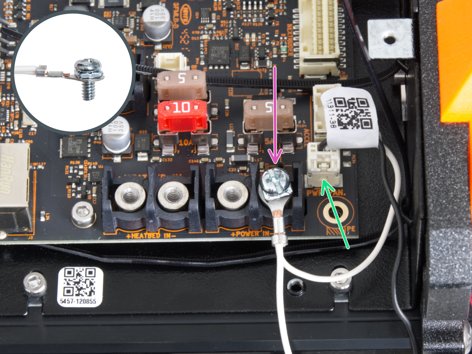
Going off the above, I disconnected the power panic cable and connected it only to the "V-" pin. I powered up the printer and it did NOT give a power panic! image0 Note that the black connector on the PSU power panic pins pulled off as I tried to disconnect my cable yesterday, which is why I could plug this connector in sideways as shown.

I believe this means the solution is simply to tie the white wire of the power panic cable to ground (or leave it on "V-" pin), leave the black wire disconnected, and the printer will no longer respond to power panics. However, this does still need to be verified. I'm not 100% sure I'm not missing something, though I did unplug the power panic cable completely and use a DMM to verify that "V-" is in fact connected to the negative rails on the PSU.

If this is the solution, then I believe I know now why early MK4's shipped with a single-wire power panic cable and the majority of them shipped with a dual-wire power panic cable. The addition of the ground wire (plus minor xBuddy board change), allows the printer to not only check for power panics, but to check integrity of the power panic cable, so that defective (or unplugged) cables are caught and the printer throws a panic.

I agree that they should add an option for users to toggle power panic checking, in case people would prefer to disable it for UPS false-positives, or don't want it for any other reason. But hopefully now there's a workaround.

jseyfert3 commented 1 year ago

Testing: I had the power panic cable plugged in normally, started a print, and then yanked the power cable. The printer gave 2-3 beeps before falling silent. I plugged the power cable back in, and it booted and then gave a "the heatbed has cooled, inspect..." error that I hit continue, and then it went back to the print screen with the "tune/pause/stop" buttons, paused, waiting for me to resume print.

I stopped the print and went back to main menu, powered down the MK4, and reseated the power panic cable so only the white wire was connected as shown above. I powered the printer back up, started a print, and again yanked the power cable. This time, the printer did NOT beep at me as it fell silent. I powered it back up and it came back to the main menu as if I had powered it down normally while not printing. In other words, the power panic did not activate, yet I was able to boot the printer and start a print.

Conclusion: Disconnect the black wire from the power panic, while leaving the white wire connected to "V-" (or any other point tied to PSU negative) will disable power panic AND disable the cable check portion of the power panic.

IBNobody commented 1 year ago

FYI: Here is the close-up of the power panic area. You will have to wait until I get off work for me to reverse engineer and provide resistor values. But this does lead me to believe that the acFault line is terminated, possibly with both a pull-up and pull-down.

image

(The PCB is only single sided, but it has at least 4 layers.)

Conclusion: Disconnect the black wire from the power panic, while leaving the white wire connected to "V-" (or any other point tied to PSU negative) will disable power panic AND disable the cable check portion of the power panic.

The heroes we don't deserve.

m-cas commented 1 year ago

Please allow me a possibly silly question: is this working because -by grounding the white line- the bkack ine has become an antenna that picks up enough noise to be read as high by the code?I did check the startup portion and the powerup check is ‘if signal low throw exception’ … given the results (no exceptions thrown) it seems that the black line has magically 2v from the air… I fully believe the results you guys got but I wonder if this is just luck when in reality it shouldn’t work. -From my phone while mobile, please excuse any errors.On Sep 26, 2023, at 21:17, IBNobody @.***> wrote: FYI: Here is the close-up of the power panic area. You will have to wait until I get off work for me to reverse engineer and provide resistor values. But this does lead me to believe that the acFault line is terminated, possibly with both a pull-up and pull-down.

(The PCB is only single sided, but it has at least 4 layers.)

Conclusion: Disconnect the black wire from the power panic, while leaving the white wire connected to "V-" (or any other point tied to PSU negative) will disable power panic AND disable the cable check portion of the power panic.

The hero we don't deserve.

—Reply to this email directly, view it on GitHub, or unsubscribe.You are receiving this because you were mentioned.Message ID: @.***>

tkircher commented 1 year ago

Conclusion: Disconnect the black wire from the power panic, while leaving the white wire connected to "V-" (or any other point tied to PSU negative) will disable power panic AND disable the cable check portion of the power panic.

Nice. Also, with @IBNobody posting that pic clearly showing that there's a resistor between V+ and V-, a decoupling cap, then a resistive divider on the other side, with two traces leading away, we have a much better idea of what's happening. And sure enough, looking at the kit assembly guide again, it only shows one wire (connected to the leftmost pin, the one with the trace leading to the via) - which I didn't even notice at the time.

https://help.prusa3d.com/wp-content/uploads/2023/06/a08bf13d40f74d30dfa3ba8877d30d13_painted.jpeg

It also shows this connecting to the rightmost pin on the PSU (V+). Just adding this for reference since the power panic connector on the xBuddy is helpfully not silkscreened with pin numbering.

IBNobody commented 1 year ago

Please allow me a possibly silly question: is this working because -by grounding the white line- the bkack ine has become an antenna that picks up enough noise to be read as high by the code?I did check the startup portion and the powerup check is ‘if signal low throw exception’ … given the results (no exceptions thrown) it seems that the black line has magically 2v from the air… I fully believe the results you guys got but I wonder if this is just luck when in reality it shouldn’t work.

It works because the black wire is pulled up, and the white wire is pulled to the black wire.

This correlates to @Crusher7485 's measurement of 2V across the black-white pair because you'd be measuring the voltage across the white-to-black pull-up while white is grounded. If @Crusher7485 measured the voltage between the connector pins at the xBuddy with the connector disconnected and GND, they would likely measure 3.3V on both pins.

Also, yes, there is a transistor in this, Q12, marked as a W1A. Pin 3 is pulled up and probably leads to the MCU.

image

image

R199 appears to be a 1k pull. R31 appears to be a 1k series term resistor between the leftmost power panic pin and Q12 pin 1 (NPN Base). R54 is a 100k resistor between power panic pins 1 and 2. R200 is a 1k pull resistor on Q12 pin 3 (collector). The rightmost power panic pin also goes to Q12 pin 2 (emitter). There's a via on the leftmost power panic pin that leads... somewhere.

image

I don't think that's right. I think I'm missing something or am misremembering. I will double-check later. (You'll have to forgive me - I have my electronics lab set up in the garage, and I'm in Texas, and it's HOT today.)

IBNobody commented 1 year ago

Also, ironically, the solution I used for my MK3S+ would seem to work on the MK4 (though I haven't tested it). I put a switch inline with the black wire and kept the white wire hooked up.

jseyfert3 commented 1 year ago

Please allow me a possibly silly question: is this working because -by grounding the white line- the bkack ine has become an antenna that picks up enough noise to be read as high by the code?I did check the startup portion and the powerup check is ‘if signal low throw exception’ … given the results (no exceptions thrown) it seems that the black line has magically 2v from the air… I fully believe the results you guys got but I wonder if this is just luck when in reality it shouldn’t work.

It works because the black wire is pulled up, and the white wire is pulled to the black wire.

This correlates to @Crusher7485 's measurement of 2V across the black-white pair because you'd be measuring the voltage across the white-to-black pull-up while white is grounded. If @Crusher7485 measured the voltage between the connector pins at the xBuddy with the connector disconnected and GND, they would likely measure 3.3V on both pins.

Also, yes, there is a transistor in this, Q12, marked as a W1A. Pin 3 is pulled up and probably leads to the MCU.

image

image

R199 appears to be a 1k pull. R31 appears to be a 1k series term resistor between the leftmost power panic pin and Q12 pin 1 (NPN Base). R54 is a 100k resistor between power panic pins 1 and 2. R200 is a 1k pull resistor on Q12 pin 3 (collector). The rightmost power panic pin also goes to Q12 pin 2 (emitter). There's a via on the leftmost power panic pin that leads... somewhere.

image

I don't think that's right. I think I'm missing something or am misremembering. I will double-check later. (You'll have to forgive me - I have my electronics lab set up in the garage, and I'm in Texas, and it's HOT today.)

It's hard to see in your picture, but does that horizontal trace connect to the bottom of R200, or pass underneath it? If it connects, where does it run to?

Second, you show R200 and R199 connected, along with "VCC?" Does R200 connect to the via I see just to the left of the upper side of R200? And that via connects to the via that the lower side of R199 connects to?

IBNobody commented 1 year ago

I need to update my schematic. R199 and R200 are indeed pull-ups to 3.3V. And the output of Q12 (labeled Q1 in that pic) goes to the gate of Q13, a P-channel MOSFET DMG2305UX. Drain is tied to a MCU pin and is pulled down by a 100k ish resistor. Source is tied to 3.3V.

image

Sorry, it's been a hot minute since I last used free schematic tools, and Scheme-It from Digikey isn't loading for me.

IBNobody commented 1 year ago

Here's a better schematic... (Edit: Fixed the location of R199 and the mystery VIA.)

image

And the explanation.

The white wire provides a GND reference to Q12. Q12 turns ON due to the pull-up R199. Since Q13 is a p-channel FET, it also turns ON (Vgs = -3.3V). The MCU sees 3.3V and registers /acFault = FALSE. The xBuddy is happy and can boot.

jseyfert3 commented 1 year ago

That makes sense for the power panic cable being connected or disconnected, causing a power panic. But while I may be missing something, I can't see how that makes sense for the normal power panic operation itself.

During power panic, the PSU pulls the black line LOW. There is now 1/2 of 3.3 volts, or 1.65 volts, on the base of Q12. I'm not the best with transistors, but the PMBT3904 datasheet I pulled up is showing a base-emitter saturation voltage of 850 mV for I_c of 10 mA (we have less than 3.3 mA). So even when the PSU pulls the black line LOW during power panic, Q12 should still be ON, which means Q13 is ON, and the MCU is happy.

So I'm either missing something (quite likely) or the puzzle isn't completely solved yet.

IBNobody commented 1 year ago

I have the R199 on the wrong node. It needs to be on the other side of R31.

jseyfert3 commented 1 year ago

Oh yeah, it would work like that!

The 2 volts I measured doesn't make sense though, should be almost 3.3 volts, unless the unknown via is connected to a resistor to ground.

IBNobody commented 1 year ago

Oh yeah, it would work like that!

The 2 volts I measured doesn't make sense though, should be almost 3.3 volts, unless the unknown via is connected to a resistor to ground.

I measured ~1.4k from the black wire pin to GND, so there's definitely something there. And ~1.4k would make sense if you were reading ~2V. Divider calc with 1k and 1.4k and 3.3V yields 1.925V.

Also @Crusher7485 feel free to post your white wire findings on Reddit. to help out others.

JPElectron commented 1 year ago

I'm late to this party, but due to my own frustrations, I finally just cut the power panic circuit out of the stock power supply and connected it as so...

PXL_20230927_152810256

PXL_20230927_152829454

Note I added that resistor at the top to keep the opto-isolator "on" from the 24v supply, and the two single stripe resistor looking things which not resistors but simply wires (see purple and blue lines in second picture)

Power is so unreliable in my area I have to run all printers on a 24V double-conversion style UPS. This was the only way I could be up and running with the MK4 and not wait for a firmware fix.

IBNobody commented 1 year ago

@JPElectron I love it. Extreme, but yeah, that would do it. You forced the optoisolator to always fire.

Also, for the record, if anyone needs to hard-solder the power panic, this net is the net that needs to be tied to V- / GND.

image

IBNobody commented 1 year ago

Just an update: This is what I created as a quick connect cable for the MK4. Not as good as a FW solution, but it will work for me.

20230930_174210

20230930_174316

It's a hardware solution to the problem.

TobbeJ commented 1 year ago

@JPElectron I love it. Extreme, but yeah, that would do it. You forced the optoisolator to always fire.

Also, for the record, if anyone needs to hard-solder the power panic, this net is the net that needs to be tied to V- / GND.

image

I think the power panic adapter cable for the silver psu should do the right thing, look at this picture: image from step 36 at https://help.prusa3d.com/guide/6-xlcd-assembly_529780#548455 in the mk3.9 upgrade guide.

IBNobody commented 1 year ago

@TobbeJ HA! Yeah, that's exactly what's going on. Awesome!

Prusa-Support commented 10 months ago

Thank you all for your input.

We are aware of this limitation at the current state of the art. As I seem to understand though, in order to bypass error Power Panic #13321 (MK4) #21321 (MK3.9), the user can short the power panic cable on the xBuddy' end. The Power Panic would not work, but there should be no error.

I haven't tried this myself and this is nothing we recommend but the result should be similar to disconnecting the Power Panic on the good old MK3. If you are willing to give it a try, please do at your own risk.

Michele Moramarco Prusa Research

DraconPern commented 10 months ago

Hopefully this will help some people here. If you have an UPS that has a 'Green mode' setting (like APC SmartUPS), you can try turning that off so that the inverter is always online.

github-actions[bot] commented 6 months ago

This issue has been flagged as stale because it has been open for 60 days with no activity. The issue will be closed in 7 days unless someone removes the "stale" label or adds a comment.

github-actions[bot] commented 5 months ago

This issue has been closed due to lack of recent activity. Please consider opening a new one if needed.