 2dom
commented
5 years ago
2dom
commented
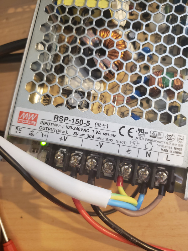
5 years ago This Looks very wrong, re-check proper power supply (>3A), thick power cables (5V at Panel!), proper grounding between ESP and Panel. If this does not do the trick try reducing the SPI Speed in the PxMatrix.h file.
 GeorgeFlorian
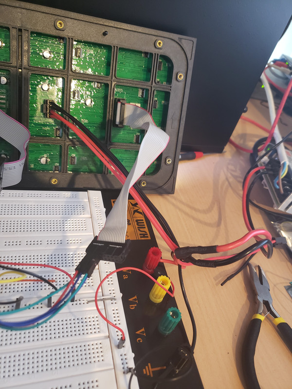
Hello !
I am trying to use a LED Display and an ESP32.
Display: 2727 SMD P5 64x32 Board: ESP32 Wrover-B DevKitV4
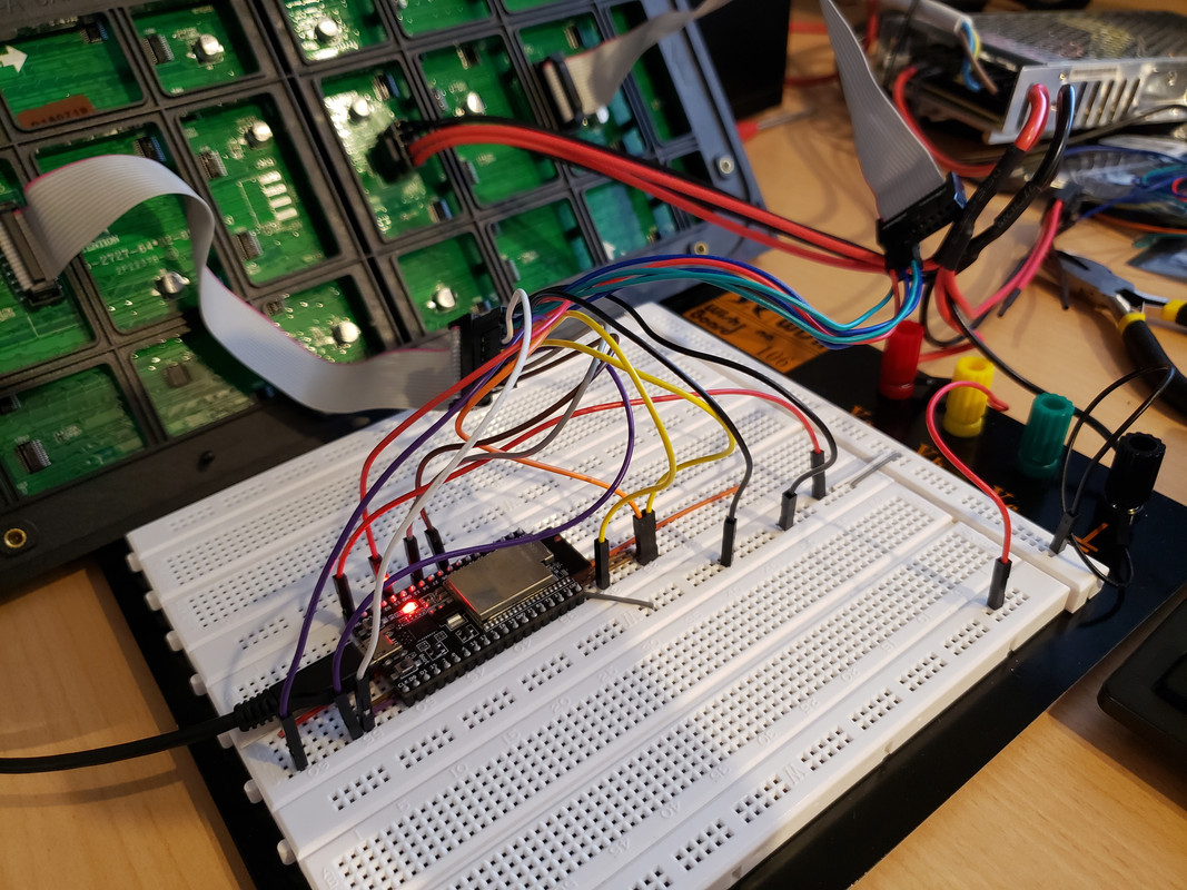
I've done the wiring as it was written in the ReadMe. I thought I did a mistake so I redid the wiring and still nothing.
I've also redefined the GPIO as follows:
define P_LAT 22
define P_A 19
define P_B 23
define P_C 18
define P_D 4
define P_OE 25
P_Eshould be marked as the GND between G2 and B on the HUB75 Matrix, right ?I've used E as GPIO 15 together with the proper constructor:
PxMATRIX display(64,32,P_LAT, P_OE,P_A,P_B,P_C,P_D,P_E);. If it's only a wire from the GPIO 15 on the ESP to the E pin on the HUB75 Matrix, the pattern_test moves slower. If grounded it moves faster. About half a row faster.If I use E as a ground and use the
PxMATRIX display(64,32,P_LAT, P_OE,P_A,P_B,P_C,P_D);constructor it behaves just like I described above when E was grounded, so it moves "faster", just like in the video at the end of the video.I've tried
display.setScanPattern(x)with all its values:LINE, ZIGZAG, ZAGGIZ, WZAGZIG, VZAGand it changes nothing. I've also used:display.setMuxPattern(x)with BINARY and STRAIGHT.STRAIGHTwould shift the rows lower and from 8bit x 4 row I would end up with 3 row instead of 4. Between commenting the function and usingBINARYthere isn't any difference, so I've ended up not usingdisplay.setMuxPattern(x).This is the
Pattern_Testexample code that I am using:Here is a video demonstrating the
pattern_test: https://youtu.be/Upmmn8KFX7sIt doesn't look right... The colors are wrong and it skips some lines. Sometimes the colors flash, I don't know why they didn't flash in the video.
What do you think the problem is ?