 blazczak
commented
3 years ago
blazczak
commented
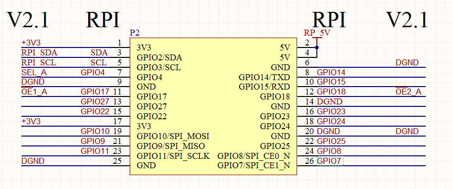
3 years ago Were you able to reverse engineer this information for yourself? Based on the schematic of a similar board in README.md and the source code for the model in question, one would assume that the power pins, the SDA/SCL and GPIO4 and GPIO17 pins are taken, the rest is unused (the video signals go through the FFC, as before). Visual inspection of the traces on the board should confirm.
The documentation for this board on Github describes 6 pins of connectivity, but the connector on the board covers 22 GPIO pins, without any pass-through. Obviously, GPIO pins are precious on a Raspi, so could anyone tell me which pins are unused, or open for re-use?