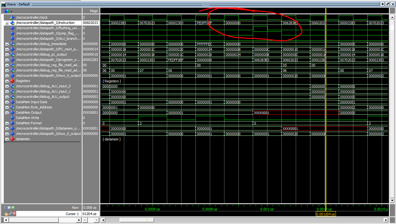
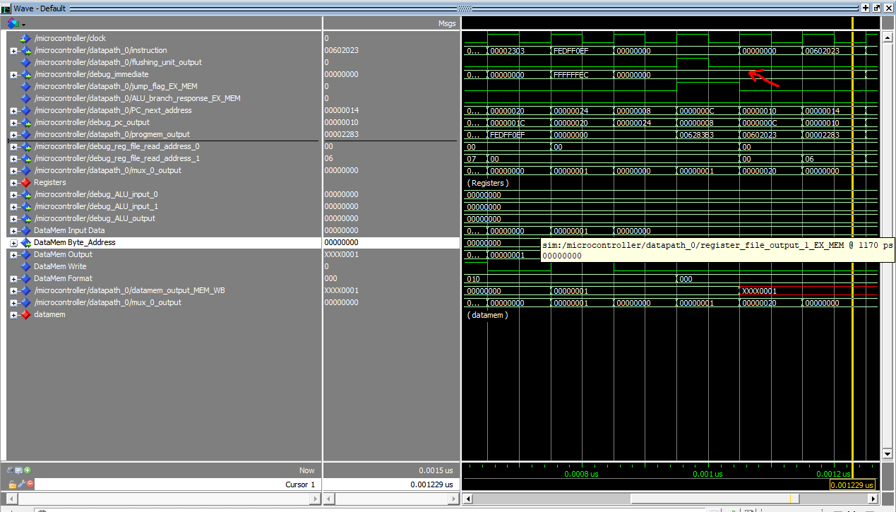
I fixed this problem by following an example from StackOverflow.


Essentially, by delaying the output by one clock, I removed the spike mentioned before. The flushing unit will now assign the flushing output of the next rising edge during the current falling edge. Because of the delay, instead of using signals from the ex/mem register, I used the OR-ed jump/branch signal from the previous stage. The flushing output will be available at the same clock as previously, but now without the spike.
Here is my modified flushing unit:
library IEEE;
use IEEE.STD_LOGIC_1164.all;
use work.all;

entity flushing_unit is
    port (
        clear, clock : in std_logic;
        flushing_control : in std_logic;
        flushing_output : out std_logic
    );
end flushing_unit;

architecture behavioural of flushing_unit is
signal internal_flushing_control : std_logic := '0';
begin

process(clock)
begin
    if falling_edge(clock) then
       if flushing_control = '1' then
          internal_flushing_control <= '1';
       else
          internal_flushing_control <= '0';
       end if;
    end if;
end process;

flushing_output <= clock and internal_flushing_control;

end architecture behavioural;
in datapath:
FLUSH : flushing_unit port map(reset, clock, ALU_branch_response or jump_flag_ID_EX, flushing_unit_output);
I also modified your Progmem interface a bit. In your original Datapath, instead of using the output of the PC, you were using the PC_next signal. Probably you were trying to use the Quartus ROM primitive, that's positive-edge-triggered by default. So I converted it into negative-edge-triggered by adding an inverter in the Progmem interface.
in progmem.vhd:
progmem_0 : progmem port map(memory_address(15 downto 0), not clock, output_data);
in datapath:
progmem_module_0 : progmem_interface port map(clock, PC_output, progmem_output);
Hello,
I tried to run my Fibonacci instructions in Simulation Waveform Editor, but I had difficulties getting the expected output. Here is my assembly instruction.
which disassembles to:
I modified the files to make it work in ModelSim, so I don't have to do 7-minute compilations every time I change the program. For some reason, "use work.all" didn't work in ModelSim, so I had to declare the components in every .vhd file.
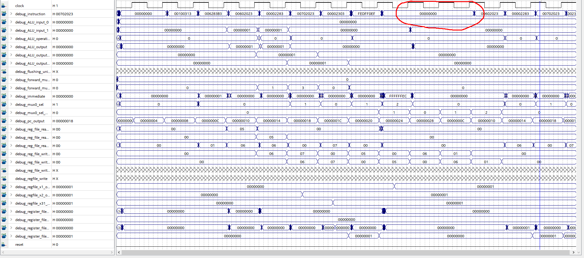
After inspecting it in ModelSim and comparing it to the Ripes simulator, it turns out that there's an excess No-OP instruction. I think this is because the pipeline register is still reset when the third rising_edge is happening. There's a weird spike at the beginning of the third clock. I solved it in ModelSim by adding a delay.
After adding delay:
However, when I do a functional simulation or a timing simulation in Quartus, the problem persists.


I haven't tried it on an actual FPGA. Probably it will fix itself, but I'm not sure because the timing simulation output is incorrect.