BeeHive-org / BeeHive

BeeHive: a flexible open hardware platform for behavioural experiments
MIT License
10 stars 6 forks source link

Question about Peltier element #12

Closed isobianin closed 3 years ago

isobianin commented 4 years ago

The previous installation of Peltier element has an L298N as a driver. The questions here are whether it is effective and are there any changes that need to be implemented? Also, there is a thermistor that is used to monitor temperature, any changes here?

Some background information. From what I have found out, the L298N can be controlled with PWM signals and that is exactly how it is done in FlyPi. However, there is a lost of efficiency when using pure PWM (a change between HIGH and LOW with different time intervals) due to the fact that this way Peltier is driven by current that changes from 0 to some max value. It is a problem because efficient cooling and heating of Peltier is achieved with current that is not 0 nor max value. Therefore, DC should be used (note 1 and note 2). It means that we need to control current flow either by filtering PWM signal or by a current regulator.

amchagas commented 4 years ago

Having a temperature sensor + peltier element would be a great add to this system! The way we developed things in the FlyPi was def. sub-optimal as it was all part of the first more "serious" interaction with electronics and as you mention there are a couple of things that could be done better:

isobianin commented 4 years ago

Hi @amchagas !

I got an additional question regarding the Peltier element that was used. Is it good and can we continue our development with it in mind? Because the more I look into this issue, the more questions arise and it will take some time to make a good Peltier driver.

amchagas commented 4 years ago

Hi! I think that model is fine, as it was a 12V 5A model. That should be enough power for most applications I think. Related to this, we have been using these two things for a makeshift incubator: Temperature control https://www.aliexpress.com/item/4000773769510.html?spm=a2g0s.9042311.0.0.3b684c4dprTUIB Peltier: https://www.aliexpress.com/item/4000216365780.html?spm=a2g0s.9042311.0.0.3b684c4dprTUIB

For the peltier we invert the wire connection so that instead of cooling down on the exposed side, it heats up.

The temperature controller is simply a relay system, and the power supply is just a regulated 12V 6A source.

Maybe this is useful for your research on the peltier drive?

isobianin commented 4 years ago

Thanks @amchagas !

Of course, it is much appreciated and I will start implementing an idea soon

isobianin commented 4 years ago

Regarding PID control, I have found this in micropython and this in python. What do you think? There are other implementations of PID algorithm but the first one does look promising.

amchagas commented 4 years ago

To be honest I have little knowledge about PID, so if you think the first option is good, let's give it a try!

isobianin commented 4 years ago

Hi @amchagas !

Just to be on a safe side, is this the latest circuitry used for Peltier control? image I plan to modify it a bit. But if it was changed at some point, I hope to see how.

isobianin commented 4 years ago

Hi @amchagas !

Here I have an important question regarding ESP32 and its PWM capabilities. From I what I could fathom, it should be possible to control PWM signal frequency and its resolution. Could we, according to this, test a code in order to find out whether it is possible to run 8 bit PWM at 312500 Hz frequency? With the given there formula, we will have (2^bit_num)-1 = (2^8)-1 = 255 levels of attenuation (we can change Peltier heating or cooling intensity by 0,4%). With such high frequency, it is much easier to design compact and reliable LC circuit.

So, if it is possible, could you please test the aforementioned code with: const int freq = 312500; According to wiki, it will either result in an error occurring and nothing working, or it will work no problem.

Maybe there are other ways of doing these but I can't seem to find accurate information regarding this question.

isobianin commented 4 years ago

To sum up the previous comment, I think of an LC-circuit for PWM signal so we can regulate current through the Peltier element via change of PWM signal width. This method is commonly used in thermoelectric cooling and motor drivers because its energy losses are minimal. It is especially relevant in our system that is thought to function while feeding from a battery. With this design in mind, LC circuitry is best to be used at high frequency so individual elements are physically smaller, thus additionally reducing parasitic parameters. So if we are able to achieve frequency around "freq = 312500 Hz", it will be great. The PWM resolution is chosen for optimal attenuation. Nevertheless, we may change this when more information is be available. That is why I think it would be rational to test the hypothesis (referring to the frequency and its bit-ing interdependence) with simple LEDs or maybe find an answer in other ways.

isobianin commented 4 years ago

It took much more time than expected. I will soon post an update with schematics and layout. Regarding the programming part, there are some news too that I hope to comment on later. Mainly, it is the PID algorithm in micropython

amchagas commented 4 years ago

Hi @isobianin! Sorry for the long time gap. I'm returning from paternity leave today, and getting messages, emails and other admin stuff out of the way.

First of all, thanks for putting so much time and effort into this! Really appreciated.

Then some short answers: Yes, the Peltier circuit is still that one indicated in your screenshot. I can test the board for the pwm today, both frequency and bit resolution.

isobianin commented 4 years ago

Hi @amchagas, welcome back! I am sorry, did not have an opportunity to answer promptly. Thanks for the information regarding Peltier. I am now (still) looking into / verifying some stuff. Just want to be sure that everything is thought through so we will have a working piece of equipment, minding that this one is crucial. Speaking about testing, it would be nice to hear results. This way we will know what our upper frequency boundaries are.

amchagas commented 4 years ago

IMG_20200916_090537 IMG_20200916_090445

On the top right corner of the oscilloscope you can see the measured frequency.

So this works nicely it seems. Also the resolution is 10 bits! I took the notes from here, which are from ESP8266 but also worked on the ESP32

isobianin commented 4 years ago

Great work! Speaking about the code, I will link one more project that I looked upon as the base of our PID algorithm. I have made there some comments but was not able to fully understand the code. And then I ran into H-bridge redesign process

amchagas commented 4 years ago

cool, will you share everything here?

isobianin commented 4 years ago

Yes, that will be the case

isobianin commented 4 years ago

https://github.com/B3AU/micropython - the main inspiration for the PID algorithm. PID.py, PDM.py and main.py are of particular interest. However, these files are written for an old version of ESP8266. Some functions, like "import pyb" are no longer used so this code may not be the "out of the box" solution. Here lies the PID.py file with my additional comments. I think they may be helpful. Original file is here If my hunch is correct, this should be quite useful, because it is ESP32 code for data extraction from DS18B20 temperature sensor. I thought that there will be one such terminal for one temperature sensor on the Peltier driver PCB. And I have actually thought to add another module for DS where there is an array of block terminals for multiple sensors (around 6, perhaps) but not right now. Speaking of which, are we going to use 3 pin block terminal for it?

isobianin commented 4 years ago

Hi @amchagas !

The Peltier driver circuit is finally finished (fig. 1). L1, L2 are taken straight from the power supply module. Hence, there is quite large margin for frequencies to be used. And yes, it is not as small and compact as it could be. On the other hand, it is easier to order lots of parts from one place (thus, there will be a discount) and with less variety in components values it is more standardized. But it may be tuned after prototyping results, if needed. image Fig. 1 - Circuitry

Circuit's working principle is quite simple. There are 2 inputs with 4 possible states (H-bridge). TC4420 driver puts HIGH or LOW signal according to its input (no inversion). PWM frequency can be more than 100kHz but it depends on the prototype testing results. There are two indicators of 12V and 5V lines (even though 5V line is used practically for temperature sensor only). MOSFETs used can be replaced with IRF4905PbF and IRFZ44NPbF (I found that they are quite common but cost more than the suggested ones). Regarding MOSFETs' temperature regime, they should work well without heatsinks. If we are to discuss shoot-through prevention, I suppose it can be solved via software means, mainly with a relatively long delay (1 sec should be more than enough) between polarity switching.

amchagas commented 4 years ago

Hi! Thanks for putting this together, it looks very nice! I would not worry too much about footprint size now, nor the price of components for this one module. let's test it :)

I agree with the idea that this would be used mostly with 12V.

About shoot-through, also I agree with adding a software delay should do the trick. We can document things and add "huge red letters" around it saying that users should be aware of reversing polarity.

I'll try to put an order for boards and components towards the end of this week so we can test this and the other updates.

isobianin commented 4 years ago

Hi @amchagas ! I am glad that we have agreed on the design aspects. A note (warning) in documentation sounds nice. I hope testing will go well.

P.s. I have gone through gas and humidity sensors and changed LED resistors' values

isobianin commented 4 years ago

@amchagas While we are on it, I have a question regarding XH connectors, mainly their max current. Does it mean that we should change connectors that are leading to/going from 12V/5A power supply?

amchagas commented 4 years ago

Hey, good catch. I was thinking about possible solutions without having to redesign things, but none of them sound great: a) use the spare pins on P15 of the central hub to make that port to be 12/12/GND/GND, in this way sharing the load to two wires for + and two wires for GND. This is a bit pushy, as each pin would still potentially get 2.5A, which is close to max rate. On the other connecting boards, we would than to switch each 12V input to 4 pin XH instead of 2 pin

b) Use a smaller power supply, maybe 12V and 3.6A, so this way, after some of the power is used by voltage converters and the ESP, we are below max rate. but this would be close as well. Could think of going even further down with the amperage of the power supply. This would also mean that potentially we would need a second power supply for things that draw a lot of power, like the peltier devices, stepper motors etc.

c) change P15 an all other 12V pins to something that is capable of dealing with the current ratings. This is a bit annoying because it will require yet another terminal type (or simply solder the cables to the place where the connectors would be). But then again, this or a) sound like a more doable/safe solution?

isobianin commented 4 years ago

Hi @amchagas ! I was thinking about an answer. In my opinion, we should take the c) approach with changing our connectors to the type that is suitable for 5A work. I believe, that it will not be that much big of a deal but what should we put there instead of JSTs? Terminals are one option but could we, say, use something along these lines: https://uk.rs-online.com/web/p/pcb-headers/5355204/ https://uk.rs-online.com/web/p/pcb-headers/1800217/ https://uk.rs-online.com/web/p/pcb-headers/1643207/ To be honest, I cannot seem to find plastic connectors similar to JST ones and I think that connector type interface, that we have (had), is the best because it is easy to use and safe (it is actually why I am hesitant about installing lots of terminals) How about aforementioned variants? What about terminals? What do you think?

amchagas commented 4 years ago

Hey!

Are you thinking about replacing all connectors? or only the ones that are doing 12V and 5A? The reason I ask is that by removing all JST connectors, we lose GROVE compatibility, no?

I agree with you that the JST ones are nice since they have they only fit in one direction, and are easy to put together.

Which is also why I considered just changing the 12V 5A connector (all the other ones are using maximally 3A from the 5V regulator, but if we are worried that this will be running on the edge, we can change the inductor value of the LM2596 to output max 2.5A), or using all 4pin JST connectors where we need to use 5A so that we have 2 wires for ground and 2 wires for V+, in this way splitting the total current in each pin?

isobianin commented 4 years ago

I thought that we are talking about 12V5A line only and it is in our best interest to make the least amount of redesign. Particularly, I referred to 12V5A line connectors only, the rest of connectors should stay as they are.

Regarding the splitting idea, it sounds good on paper. Have you already tried this design trick? As for me, I am not sure that those pins will balance amperes equally. To back this doubt, I have not seen much PCBs and other projects where current is split in the way you described and there is probably a reason. But it may be just me.

To sum up, I agree with you on your idea to change only 12V5A line connectors or test whether 2 JST connectors can split the current. But even if they can, do we really have a guarantee that it will work okay when the setup will be used by other researchers?

amchagas commented 4 years ago

ok, good we are on the same page about only changing the one plug 😄 Here is an example where I have seen people splitting current via a couple of cables

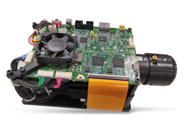
This is a device we use in the laboratories here, a light projector that requires LEDs with a bit of higher power. The cables you see on the left bottom side of the image are power cables that go to the LEDs below the PCB. Just for completion, the LEDs in that case are being switched on and off several times in a display frame (so, several times within one frame in a 60fps display).

The device is this one https://www.mouser.co.uk/new/texas-instruments/ti-dlpdlcr4710evm-g2-module/

If you think it is better to change the connector and not have the parallel cable solution, I am also happy with that!

From the options you sent, I like these: https://uk.rs-online.com/web/p/pcb-headers/5355204/ https://uk.rs-online.com/web/p/pcb-headers/1643207/

Which seem to maintain the orientation feature. The question is also if we need them to be 4 pin connectors or simply 2 pin connectors, since we are only having 12V and GND there. (could even have a 3 pin connector with 12V, 5V and GND - just an idea, we don't have to think about this now)

isobianin commented 4 years ago

I see now. I think I will just have to look into this topic in more detail just to be sure. As I said before, if we can use our system without much change (pretty much, only add one connector to the recent Peltier driver), it will be outstanding

isobianin commented 4 years ago

Hi @amchagas ! Regarding the question about JST connectors and the current splitting. This question just stuck in my mind for days. I suppose that it will work. Ideally, if we have two lines (or N lines), current will be split evenly through all of them because they all have equal line resistance as R=0 (it is zero, but it is equal). In the real application, we have our traces and wires resistance that is small but will affect the current transmission. If two wires and their respective traces are identical in length, diameters, etc., they will split the current evenly. In our case, I believe we are going to and up with something like 2.6 and 2.4 A on lines. I do not think that we will end up with current higher than 3A, unless we use only one connector.

However, I have checked the original design and there is actually another question. Maybe we should put a barrel jack connector on Peltier driver? This way we get all 12V5A power? But also leads to another question that maybe we need a 12V5A breakout?

Maybe it is a bit vague but it just dawned on me that something is not particularly right.

isobianin commented 4 years ago

Basically, the way it works now is that we have a single 12V5A line that is coming directly from the main hub. Actually, I do not think that it can go above 3A in the current setup, unless we use the main hub without ESP (so it will become a 12V5A breakout). We designed our LED arrays in a way that they can take either 12V or 5V lines. Again, highly unlikely that they will go above 3A so there is no problem here.

The way it worked before, there had not been enough current supplied to make the Peltier heat or cool all the way (all we need for it to go up about 50°C). If this is right, maybe we can even left it as it is because there is no need to use it in full power mode? Or we can add another Peltier driver with barrel jack specifically fro those application where Peltier (or something else) will be needed (or simply add a place for barrel jack onto existing pcb layout)?

amchagas commented 4 years ago

Hi @isobianin !

Thanks for spending more time thinking about this.

I did make a little test setup, like we discussed over skype. Basically,

Results were in line with the idea that current will distributed unevenly since the length of the wires compared to the wires+ammeter is different.

I also ran the system without the ammeter for 10-15 minutes full on (which is in a way different from our application since most likely will always have the ESP and the 12 to 5V converters running, which makes the total current to the peltier smaller than 5A), and watched for heating. But the wires and plugs didn't heat up significantly.

amchagas commented 4 years ago

about your point of a barrel jack, is the idea to make it possible to power it with a complete independent power supply? And the issue with having the power coming from the main hub is that we would not get enough power anyways from it to properly run the peltier?

I think a good test here would be for me to actually solder the boards, and do a real test to see what the peltier actually gets when the system is on and more things are connected to it.

But I suspect your rationale is correct, maybe this is going to need an extra/different power supply...

isobianin commented 4 years ago

Hi @amchagas ! Thank you for conducting all the necessary experiments!

Glad to hear that the results were predicted quite accurately. And now we for sure know that we in fact can use two JST connectors without worries (but, as I stated above, we have to warn a user somehow that two plugs should be plugged in simultaneously)

Regarding questions: 1) Yes, I think it would be rational to add barrel jack for those applications where full power is needed. Basically, a user will have a choice whether to use one JST connector from the hub (approx. 30-50% of total power) or to use dedicated PS for 100% power. 2) I think that it may be just enough power to conduct behavioural experiments (when a Peltier is getting warm, but not hot or ice cold) but not enough to work at full potential.

The testing sounds intriguing. I guess that is the only way to find out. On the other hand, I think we thought through all the variants that may happen, did we not?

isobianin commented 4 years ago

Hi @amchagas !

Regarding barrel jack connectors. Basically, I have been trying to come up with something that enforce minimum changes to the current design and I guess that there is a way out. The last time we have talked about 12V5A breakout board. So I think that it is the only thing that is missing. I think it should consist of 1 barrel jack and an array of JST connectors. As for the Peltier driver, we will simply add there another JST connector and that will be it. If we want it to work in full power mode, we simply connect its 2 JST to the 12V5A breakout (we already have a tangible proof that it will work) To sum up, all we need is to add another JST connector to the Peltier driver and design 12V5A breakout for powerful applications (or even unconventional use). But it in no way does this imply that our system needs 2 power supply, the opposite actually. I believe that even without additional power supply our system will work just fine for behavioural experiments (as we discussed before)

isobianin commented 4 years ago

Hi @amchagas !

A new 12V5A breakout is added. It is quite simple: features 9 outputs and an LED indicator. Also, I have added a warning sign so there is no confusion with connectors (at least, there will be a lesser chance that something will catch up fire) (fig. 1) 12V5A PCB Fig. 1 - PCB design

amchagas commented 4 years ago

Hi @isobianin ! This looks quite nice, I now understand your solution, makes total sense! One comment: I wonder if replacing 2 pin JSTs connectors by 4 pin JSTs connectors for the 12V lines would be sensible? So that users are by default using the connector/cable combination (I am thinking 2+ and 2gnd lines per connector) that will allow them to use 12V 5A power, without having to think about it? In tthis board above, instead of having nine possible connectors, you'd have 4, which should be still enough I think?

isobianin commented 4 years ago

Hi @amchagas !

I see what you mean. However, there are two obstacles:

1) main hub and switch arrays will be changed accordingly. With the switch arrays, they will lose their ability to be used for 5 and 12v from one connector. Not a big problem since there is a plenty of space to add another power connector but then somebody could connect both 12v and 5v there, if two connectors were to be added 2) a minor issue, but now it will become possible to accidentally connect 12v line into signal connector. Could be solved by going with 3 pin connector but that wouldn’t be that great from a manufacturing/ordering parts perspective

To sum up, we need to consider issues above. I can look into how to incorporate these changes and see what we will end up with.

amchagas commented 4 years ago

Hi!

good points, I would leave things as they are then!

isobianin commented 4 years ago

Hi @amchagas !

Regarding PID control, there is progress. Here is a file for testing.

First of all, all coefficients are subject to change. However, it still should work with but some overshoots or undershoots. I have programmed it to use D1-4 connector or IO2 to send PWM towards Peltier and D2-3 connector IO0 to receive data from ds18b20 temperature sensor. The main idea of this algorithm to smoothly vary duty cycle relative to PID output (to put it simply, it is a PID controller with pseudo-analog output).

From the programming perspective, I believe (and there are my comments all over the document) it is possible to make this file as a class, so it will be easier to use it afterwards. I hope that it is a good idea because I have not yet practiced writing object oriented programs with the use of classes.

I tried to make the program output data to a plot but it would require additional modules or GUI. For now it just outputs an array of results aside from the information that will be put up on the screen.

One important note that a variable "run_time" limits the amount of time the program is running (for now, it is 10 mins). I chose not to tinker with it and leave it as it is now. The code auto-adjusts PID parameters every 1 second.

The PWM frequency chosen is 75kHz and there is no changes in PWM resolution. I think it all can be adjusted after we verify that the code works as intended

amchagas commented 4 years ago

Hi @isobianin! Thanks for putting this together. I can set it up tomorrow and see how it runs. Once we are happy with that, turning this into a class makes sense, so that we can call more than one sensor, etc.

amchagas commented 4 years ago

Hi Ihor, I finally got some better testing time today: Testing all parts individually works well. I mean, the temperature sensor sends in data and turning IO2 to full on gets the topside of the peltier to heatup.

Then I must have done something wrong with soldering components on the other line as turning IO15 fully on heats up both MOSFETs (Q1 and Q3 I think), but doesn't cool down the topside of the peltier element.

Since IO2 was working, I tested the PID using that channel, but even though I could see signals coming from IO2 in the oscilloscope, they didn't change over time, the PID coefficients also remained the same, so I would like to change initial parameters tomorrow and see what that does, together with debugging the changes I made to the code (as the initial version used numpy, which is not available for micropython)

Then some other problem ocurred and the ESP32 I was using fried.. (really puzzled about this one as nothing changed while testing) i have another one to test thigns tomorrow and ordered more to have as backup.

amchagas commented 4 years ago

About the other issue in this thread, the power connectors, I think having 2 pin connectors is a good idea to prevent people from connecting the 12V power line to the signal and/or 5V lines. At the same time, just having the same connector on the main board is nicer for production/design and if things are properly labelled, people should not make that mistake? How do you feel about this one? Would you like to choose one and we go with that?

isobianin commented 4 years ago

Hi @amchagas !

I was thinking about your questions/results and I believe that things are not that bad. First of all, I am analyzing why ESP32 got fried. Minding the fact that I tried to include some protection into the circuitry, I identified some possible culprits:

1) First and foremost, Q1 and Q3 are heating which means that they are open thus creating a short circuit. It is happening because I missed one thing in the code - driving the opposite pin to low. If IO2 = 1, IO15 = 0, or IO15 = !IO2. Hope that this will solve it

2) Soldering. This is highly unlikely but it is worth checking

3) Reverse current. Peltier is not an inductive load and there should not be any reverse current on its side. Even if there were, MOSFETs have internal diodes. The gate-drain capacitance, on the other hand, is present but that is why there are two resistors. 1k is helping to quickly discharge this capacitance to GND or 12V line and another small resistor reduces spikes or current produced by this capacitance (also lowering TC4420 output noise). Even if the reverse current were to go over resistors, it would meet with internal MOSFETs of TC4420 which cuts the line off. If that is not enough and this is the problem, well, we could add some Schottky diodes and/or optocouplers (but lose high frequency) but I hope that it is not the case.

Regarding the 12V line, I agree with the 2 pin connectors as we had spoken about (especially, safety). The potential problem is finding enough space on the Peltier driver and the main hub and that is why I thought about doing it with 4 pin connector. I will look into this more thoroughly and we will see how it goes. And, indeed, I too think that we should limit the amount of different connectors and components in general so it is easy to order them

isobianin commented 4 years ago

An update. If it is Q1 and Q3 that are problematic, maybe this part of the PCB is the case: image Fig. 1 - Q1 and Q3 Maybe some solder got on their tracks. What about the other pair of MOSFETs?

amchagas commented 4 years ago

Hi, It is indeed Q1 and Q3.

I checked one unpopulated board and it doesn't seem that the traces are an issue. IMG_20201118_165617 IMG_20201118_165602

Also the populated board, the solder looks fine.

the other MOSFET pair works fine so I can test the PID on that channel/pair

isobianin commented 4 years ago

Hi @amchagas , thanks for the information.

I will inspect the design of the PCB once more and look for things that may have caused the problem.

isobianin commented 4 years ago

Just to be on the same page, I know it will sound very generic but Q1 is P-channel and Q3 is N-channel and they are both facing the right direction? I ask this because, sadly, their Q2 and Q4 counterparts are not placed symmetrically

isobianin commented 4 years ago

Hi @amchagas !

I have been thinking about the heating mosfets and there is one more thing we need to look out for.

If MOSFETs are heating up that means that their gates have enough voltage on them to be opened. In case of this specific transistors, possible voltages are 5...7. Therefore, we need to determine how 5...7V are appearing on the gates line/track.

My guess is that it is the TC4420 that is malfunctioning. The Peltier driver is powered mostly by 12V line and 5V is used for temperature sensor and sending signals to TC4420. In case we have 5V on gates line, possible problem is that TC4420's feeding system does not provide 12V to the line. If there is 7V or something in between 5V and 7V on the line, it means that 12V line is interfering with 5V signal line thus resulting in 7V on the line (12-5=7V). I think this is possible if the internal diode, which is connecting 5V signal and 12V power lines, is destroyed (fig. 1) image Fig.1 - TC4420 structure

If TC4420 is not the case, then there is another way how 5...7V are getting on the track/line. Maybe, a solder paste got on the track somewhere on the PCB

amchagas commented 3 years ago

hi! I have removed Q1 and Q3 and installed new ones. Checked orientation and both the new install and the old one were in the right orientation.

I tested the whole system with PID code again and they don't heat up, but also do not change the peltier temperature. I tried playing around with the initial coditions of the PID code but that didn't bring many changes as well.. I tried using this to get a feel for initial numbers, but as I mention did not get much far. It could be that I messed something up when I adapted your code to be micropython compatible... will have to debug a bit further... I upload the code I have so far

isobianin commented 3 years ago

Hi @amchagas !

Does it mean that the hardware part is alright? Have you tested peltier with simple high and low signals on respective sides?

The one thing that I thought of that might be associated with the issue is TC4420's output, mainly the fact that it is not inverted. Therefore, whenever it receives HIGH signal it will duplicate it at its output. This leads to the fact that high side MOSFET is off, while the low side is on. With this in mind, maybe the wrong pad of the peltier is being heated up? Should we opt to change TC4420 to the inverted variant?

If hardware is alright, I will at the very least continue with the development of an LED driver and look into #18 issue.

amchagas commented 3 years ago

Hi @isobianin, yes the hardware seems to be fine. More testing tomorrow.

I am not sure I follow your point about the wrong side of the peltier being heated up... I mean, considering we have an h-bridge configuration it should just be the case of switching which side is on from pin1 (io2) and pin2(io15), no? and this should then change if a specific side of the peltier is heating up or cooling down?

For the LED driver are you planning to develop something from scratch or base it on some open source design? Sorry I do not remember if we discussed this!