BelfrySCAD / BOSL2

The Belfry OpenScad Library, v2.0. An OpenSCAD library of shapes, masks, and manipulators to make working with OpenSCAD easier. BETA
https://github.com/BelfrySCAD/BOSL2/wiki
BSD 2-Clause "Simplified" License
944 stars 111 forks source link

Phillips heads : other shapes, JIS , improved driver tip #658

Closed sbridger closed 1 year ago

sbridger commented 3 years ago

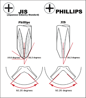
The current Phillips is the punch tool shape. Actual driver bits are slightly different to the punch tool / recess.

Just thought I would create this issue as somewhere to link the info for other heads/drivers, for future reference. Not really expecting anyone to implement it.

JIS shape is somewhat different to Phillips, and would be nice to also have JIS (since that what I am actually needing for this job)

This is an (expired) patent for an improved Phillips driver bit.

Has POZI dimensions

adrianVmariano commented 3 years ago

In screws.scad the screw head data has depth, width and diameter for the philips recess, but there's no code that knows how to turn that into a model, so a crude model is used. (I never understood the geometry well enough to figure out how to define the recess from those parameters.) The problem is that unlike other recess types, there's no "#2" recess. There's a #2 driver but every recess has its own specs, and a supposedly compatible driver number. Proper support for JIS would therefore require an analogous table of JIS recess dimensions for every supported head type, as well as some model for how to turn JIS recess dimensions into a model.

Modeling the driver is presumably easier, since there are just a handful of driver sizes. Were you interested in modeling the driver or the recess?

One thing that would be good is a model that actually uses the phillips parameters to construct the recess.

sbridger commented 3 years ago

I was referring to phillips_drive.scad. It has the proper Phillips parameters for the recess / punch dimensions.

I am designing a bit for my multitool, that oddly only has a #1 Phillips tip, when almost all bike screws are #2. I realised that while PH2 works, the screws are actually JIS heads, so I may as well make the tip JIS.

adrianVmariano commented 3 years ago

I don't really understand Phillips drive particularly. The tables of specs can be unhelpful at revealing the fundamental principle behind something. Is it possible to create correct phillips recesses by "punching" out from a fixed size phillips shape (for each "number" size of phillips)? It's not clear to me that this is the case, though it sure would simplify matters.

But it sounds like you want to model the driver, not the recess. Do drivers have a well-defined spec? It sounds like actual drivers may be all over the place. But also, looking at what phillips.scad produces, those look like masks to create a recess, not a driver: they are too pointy at the ends to be a driver. The drivers all have a blunt end, while the recess has a pointed bottom.

Do you have some reference that you think has sufficient information to define the full geometry of a phillips driver and JIS driver? Everything I see purporting to define these shapes leaves me feeling like I don't have enough info to actually produce the shape.

sbridger commented 3 years ago

Yeah it's pretty confusing looking at the drawings, but I think it's all in the refs I gave. Screw heads are actually made by punching. So if you want to make an accurate head in openscad, just use phillips_drive.scad to make the hole. What is not specified is how deep you want to punch it. You can punch PH2 into quite a small screw head if you want, just don't punch it too deep. This is what japanese do: most common small screws have JIS#2 , when you would guess from looking at the size that #1 would be used. It is pretty common to find a narrow screw hole that has a #2 head down it, but all your #2 drivers are too fat

adrianVmariano commented 3 years ago

Actually if you look in screws.scad you'll see that I have diameter, depth and cross thickness for the phillips heads---so it sounds like excess information if actually just depth and driver number is needed. Like I said, part of the problem is being unable to tell which information is actually fundamental and which information is derived. The code right now is in fact "punching out" screw heads using the depth from specs for the screw heads.

But which document do you think provides sufficient information to produce the recess shape? The first one comparing JIS to phillips seems to say that the philips side walls are curved, which our model is not. I don't think I've seen something that explains how the shape changes as you go up. The second thing with the patent is not what I'd call readable---does it somewhere explain the shape of the recess (not the new innovative driver shape)?

But I do think that if you want to make a driver you need to cut off the end of the phillips_drive.scad model. I think the main thing standing in the way of doing JIS is actually knowing what it is. If you could supply code for it we could add it.

adrianVmariano commented 3 years ago

I tried to confirm that the diameters follow the chart if I sink the model to the listed depth, and they do...but not quite. the recesses are undersized by about 0.01 inches systematically. Some further checks suggest that the dimensions are not quite right, like I tried to confirm the "g" value and it is a little bit off.

adrianVmariano commented 3 years ago

The Pozidrive standard you post has actual standards for the Phillips and Pozidrive, but not JIS. I don't see a document that gives standards for JIS and I have not succeeded in locating such a document anywhere.

In examining phillips_drive.scad and comparing to the standard, I found two errors, one huge error one one small error. The huge error is that the angle between the wings was around 70 deg instead of 92. So I've fixed that. I also now understand the spec pretty well, so if you can turn up a spec on JIS it will be pretty easy to implement, I think. The hard part is finding the spec. (Or you can pay $78 for it.) The bike shop info is not complete. I need a table of values for the width of the tip, tip angle (which is maybe different from phillips), radius between wings. I don't know how to position the cutout without this information, and I can't "guess" it from the Phillips spec because the point of reference has moved.

It seems like implementing drivers may be a whole separate thing. That patent is probably a good guide for someone willing to slog through it. It describes a curved cutout, unlike the recess standard where the cutout is straight. The drivers are cut off differently at the tip, for example, JIS apparently straight across and Phillips....some other way.

sbridger commented 3 years ago

Can you push you changes to your github clone?
Yes I saw an angle error too

    //p1 = [e/2, adj_ang_to_opp(e/2, 90-alpha/2)]; //inner bevel
    p1 = e/2*[1, tan(90-alpha/2)]; //inner bevel   
    //p2 = p1 + [(shaft-e)/2, adj_ang_to_hyp((shaft-e)/2, 90-(gamma/2))];
    p2 = p1 + (shaft-e)/2 *[1, tan( 90-(gamma/2))];

Having trouble finding a definitive jis dimensions, and lots of conflicting statements about what is or isn't different.

I print out patents, then use scissors and gluestick to put the text back onto the drawings. Then it starts to make sense. The essence of the B&D patent is a stepwise change of the 92 degrees at the tip to 104 at the top, to allow for deformation of the recess under heavy torque.

adrianVmariano commented 3 years ago

My changes are pushed to my clone. Your p1 redefinition is identical to the original. Your second one corrects the large error I found. I also found that there were issues rendering the model as designed due to the stacked cylinders, so I changed that. The other error I mentioned above is in positioning the cut-outs. They were positioned so that the "b" distance was not quite right.

Is the patent a stepwise change or a continuous change? I thought it was a smooth curve and they were showing sections to indicate how the angle changed. Of course, we don't have any definitions of drivers, I think, just recesses. I think we'll be renaming the modules to something like phillips_mask, torx_mask and so on and putting them all in one file.

I feel like some of the JIS talk is about the driver, not the recess. Like the bit on the bike shop site about a flat side vs curved side. That's about the driver, perhaps a reference to the patent. I'm pretty sure that JIS primarily differs in the shape of the cutouts (radius instead of clipped at an angle), but this makes it unclear how to position the cutouts. Presumably the "b" value is smaller.

Most info I've found is here:

https://www.garagejournal.com/forum/media/jis-b-4633-vs-iso-8764-1-din-5260-ph.84492/

but it looks like it's about the driver and not the recess.

sbridger commented 3 years ago

my best take on the JIS is that it will be the exact same as PH, except for the 140 degree inner bevel which will is replaced by a deeper 92degree cut to the 60um radius point.

I think this might apply to the recess too , which would explain PH2 driver not fitting. It is very confusing as JIS/DIN have been rolled into a single ISO now. Were the recesses different before but have changed now?

I have implemented curl out, and modular profiles now, so I will have a look at your changes, and try to get my take on JIS going.

Then PZ should be easy to add for anyone who wants.

adrianVmariano commented 3 years ago

So you think the radius on JIS is the same for all sizes? It's not clear that 60 microns even counts as a radius. I would probably just model it as a 92 deg angle, but then how do you position the cutout? I wrote code that makes a cutout shape with a radius---theoretically this is needed for PH#0. But I'm not sure it's worth the complication of putting it in.

When you say "curl out" you mean the increasing angle for the driver? That page I referenced shows slight changes between the JIS and ISO, but key info is lacking.

I haven't managed to figure out the PZ spec, though also I haven't tried hard. I've also never seen a PZ screw, though I do have some PZ bits I should probably throw away. I was trying to do square drive, which seems like it should be simple, but I ran into similar spec issues. The only specifications I can find seem to be inconsistent with my actual square drive tools and screws. So not sure what to make of that. And apparently the sides are tapered by a secret amount, never revealed anywhere.

sbridger commented 3 years ago

curl-out image

adrianVmariano commented 3 years ago

Ah. That looks good for how a driver should look. I see you also cut the tip off, so it looks like an actual driver. I was also wondering if the drivers are supposed to have undersized dimensions. It wouldn't matter for Phillips because it can just engage less in the recess, but for something like torx or allen, the drivers at least are parallel sided.

Any idea how standard shaft diameters are? I found a list and made it the default but don't know if it should be the forced standard, or if shaft diameter should still be an option.

sbridger commented 3 years ago

I changeg ang1 to 18deg per this table (A2). Some images show the JIS end square, but maybe that is just a driver feature, as the tables say 18-19deg There do seem to be diameters in some of the tables.

However it is definitely a needed option when making a driver, as it is common for japanese gear to have a #2 down a hole that is smaller than 6mm.

adrianVmariano commented 3 years ago

I think this change is just for the driver, not for the recess, right? Same as for the curve away---only for the driver, not the recess mask.

I was thinking of trying to order some Vessel JIS bits to see what they look like. They seem to be considered the ultimate in JIS drivers.

When you say shaft is a needed option (for a driver) you mean that some japanese screws are in holes that a 6mm shaft wouldn't fit in? Ok. I lean towards thinking that there should be a shaft argument only for the driver module and not the recess mask module. The only thing that can go wrong with the recess is your shaft was too small and you get a wrong recess (with cylindrical side walls).

sbridger commented 3 years ago

I have already added the default shaft diameters D and ISO lengths L tables now, assuming 3.2mm for PH0.

I think this change is just for the driver, not for the recess, right? Same as for the curve away---only for the driver, not the recess mask.

I assume that for all real heads, the recess will always be shallower than the drive cone part, so the curve away doesn't matter, it's always beyond the recess. At the moment I think recess-punch and driver are the same, as I think the intrinsic taper takes care of tolerances.

[The B&D patent is a driver only design, but this code can't generate it anyway.]

adrianVmariano commented 3 years ago

The curve-away will probably make rendering slower, though whether by a significant amount I couldn't say. It's unlikely somebody will have a model with a dozen drivers in it, so you can make the curve away fairly nice looking (add more facets than you showed above) without it being a problem, but if it increases render time and somebody has a model with a bunch of screw heads that could make things slow.

The recess and driver are not the same. The recess comes to a point. The driver has a blunt tip. This difference is important to ensure that the driver fits, I think. (There may also be fabrication issues I don't really know about that make it easier to punch with a pointy thing?)

I actually question whether the recess mask should have any shaft on it at all, since if you're using that part, you're doing it wrong. Length should then just be to the top of the angled portion.

I found a 3.0 shaft diameter for PH0 on some table. Do you think 3.2 is better? Presumably I should use the largest diameter anybody lists as the diameter for recess masks. I just found a table that gives 5 for #1 shaft, which is bigger than the 4.5 I have listed there.

adrianVmariano commented 3 years ago

I revised the code to only generate the actual bit tip and tweaked the cutouts. It reduced render time by about 30%, it looks like.

sbridger commented 3 years ago

OK so I see in the mated cross-section drawing here that the recess is shown with ang1=28degrees, but the tip with ang1=19degrees. So we do need a tip/recess switch. I have added isdriver=true

For rendering screws in assemblies, a minimal approximation to the shape is all that is needed if speed counts. (An accurate rendition is only needed to make tools) You might want to think about how to do this - I am only interested in the accurate tooling case. I suggest a param like 'isaccurate' or 'isfast', or perhaps a totally separate function for approximately rendering screwheads

adrianVmariano commented 3 years ago

I'm not sure if the final interface is best done through one function with flags or two functions. My latest code is pushed, by the way.

sbridger commented 3 years ago

followed your swap of x<>y as it suited curl fn.

Got my take on JIS going image

stillnot reconciling all dimensions though, think about it for a while,

adrianVmariano commented 3 years ago

Yeah, swap of x and y just tidied the code a bit since the profile as it was appeared in the wrong orientation and needed to be rotated 90 deg.

Looking good! Do you have parameters to make the JIS recess? I assume it should be the same except for the end angle. Being able to compare the two models might be a way to gain confidence that JIS is correct, since presumably the wings should line up if you're away from the center. And the phillips driver as well? I imagine the only thing we really need for the phillips driver is to change the current code end angle and add the curl out.

adrianVmariano commented 3 years ago

Is the driver code ready to go?

adrianVmariano commented 2 years ago

sbridger, what's the status on the JIS driver you were working on?

revarbat commented 2 years ago

Ping @sbridger

adrianVmariano commented 1 year ago

@sbridger Are you still interested in the JIS driver issue for BOSL2?

It seems like we need to decide the fate of this issue. It's super hard to get information about JIS screws. It does appear that JIS merged with ISO and redefined their screws to be the same as regular phillips. I poked around a little bit and had a lot of trouble finding any info.

I looked at my Vessel driver, which is always held up as a great JIS example, and it looks like the phillips drivers, with two bevels in the base of the cross, not a tiny rounding in there. This actually matches my wera driver.

image

So there's an image showing the contrast and my "JIS" driver looks like the RH picture, not left hand.

And here's an article about JIS no longer seeming to exist: https://www.webbikeworld.com/hozan-jis-screwdrivers-review/

So I guess the questions are:

Do we want to build in support for drivers in general, as distinct from driver masks? Slot drivers are tapered, unlike slot heads. Phillips has a different angle at the end. Torx and hex should have $slop or something. That is, the driver and recess can't be exactly the same size. And do we care about trying to implement the (old?) JIS driver standard? Can we even tell what its specs were? If it is flat wings with a 60 micron radius it seems appropriate to model it as simply flat wings meeting at a point. But I seem to recall this created an issue for positioning some other part of the recess.