Bodmer / TFT_eSPI

Arduino and PlatformIO IDE compatible TFT library optimised for the Raspberry Pi Pico (RP2040), STM32, ESP8266 and ESP32 that supports different driver chips
Other
3.54k stars 1.02k forks source link

RP2040 andTouchscreen works with Earle Philhower's board package but not with the official Arduino mbed board package #2687

Closed ryanaukes closed 7 months ago

ryanaukes commented 1 year ago

Hello,

I am trying to use this library with my RP2040 microcontroller and ILI9341 screen with touchscreen and SD card reader. Currently I only connected the TFT screen and touchscreen pins.

Connected as follows: TFT VCC -> 5V of PSU TFT VCC -> GND of PSU and RP2040 TFT CS -> pin 20 TFT RESET -> pin 19 TFT DC -> pin 18 TFT MOSI -> pin 3 TFT SCK -> pin 2 TFT LED -> 5V of PSU TFT MISO -> pin 0 TFT T_CLK -> pin 2 TFT T_CS -> pin 21 TFT T_DIN -> pin 3 TFT T_DO -> pin 0

This is what the file called 'User_Setup_Select.h' looks like:

// This header file contains a list of user setup files and defines which one the
// compiler uses when the IDE performs a Verify/Compile or Upload.
//
// Users can create configurations for different boards and TFT displays.
// This makes selecting between hardware setups easy by "uncommenting" one line.

// The advantage of this hardware configuration method is that the examples provided
// with the library should work with immediately without any other changes being
// needed. It also improves the portability of users sketches to other hardware
// configurations and compatible libraries.
//
// Create a shortcut to this file on your desktop to permit quick access for editing.
// Re-compile and upload after making and saving any changes to this file.

// Customised User_Setup files are stored in the "User_Setups" folder.

// It is also possible for the user tft settings to be included with the sketch, see
// the "Sketch_with_tft_setup" generic example. This may be more convenient for
// multiple projects.

#ifndef USER_SETUP_LOADED //  Lets PlatformIO users define settings in
                          //  platformio.ini, see notes in "Tools" folder.

///////////////////////////////////////////////////////
//   User configuration selection lines are below    //
///////////////////////////////////////////////////////

// Only ONE line below should be uncommented to define your setup.  Add extra lines and files as needed.

//#include <User_Setup.h>           // Default setup is root library folder

//#include <User_Setups/Setup1_ILI9341.h>  // Setup file for ESP8266 configured for my ILI9341
//#include <User_Setups/Setup2_ST7735.h>   // Setup file for ESP8266 configured for my ST7735
//#include <User_Setups/Setup3_ILI9163.h>  // Setup file for ESP8266 configured for my ILI9163
//#include <User_Setups/Setup4_S6D02A1.h>  // Setup file for ESP8266 configured for my S6D02A1
//#include <User_Setups/Setup5_RPi_ILI9486.h>        // Setup file for ESP8266 configured for my stock RPi TFT
//#include <User_Setups/Setup6_RPi_Wr_ILI9486.h>     // Setup file for ESP8266 configured for my modified RPi TFT
//#include <User_Setups/Setup7_ST7735_128x128.h>     // Setup file for ESP8266 configured for my ST7735 128x128 display
//#include <User_Setups/Setup8_ILI9163_128x128.h>    // Setup file for ESP8266 configured for my ILI9163 128x128 display
//#include <User_Setups/Setup9_ST7735_Overlap.h>     // Setup file for ESP8266 configured for my ST7735
//#include <User_Setups/Setup10_RPi_touch_ILI9486.h> // Setup file for ESP8266 configured for ESP8266 and RPi TFT with touch

//#include <User_Setups/Setup11_RPi_touch_ILI9486.h> // Setup file configured for ESP32 and RPi TFT with touch
//#include <User_Setups/Setup12_M5Stack_Basic_Core.h>// Setup file for the ESP32 based M5Stack (Basic Core only)
//#include <User_Setups/Setup13_ILI9481_Parallel.h>  // Setup file for the ESP32 with parallel bus TFT
//#include <User_Setups/Setup14_ILI9341_Parallel.h>  // Setup file for the ESP32 with parallel bus TFT
//#include <User_Setups/Setup15_HX8357D.h>           // Setup file for ESP8266 configured for HX8357D
//#include <User_Setups/Setup16_ILI9488_Parallel.h>  // Setup file for the ESP32 with parallel bus TFT
//#include <User_Setups/Setup17_ePaper.h>            // Setup file for ESP8266 and any Waveshare ePaper display
//#include <User_Setups/Setup18_ST7789.h>            // Setup file for ESP8266 configured for ST7789

//#include <User_Setups/Setup19_RM68140_Parallel.h>  // Setup file configured for RM68140 with parallel bus

//#include <User_Setups/Setup20_ILI9488.h>           // Setup file for ESP8266 and ILI9488 SPI bus TFT
//#include <User_Setups/Setup21_ILI9488.h>           // Setup file for ESP32 and ILI9488 SPI bus TFT

//#include <User_Setups/Setup22_TTGO_T4.h>           // Setup file for ESP32 and TTGO T4 version 1.2
//#include <User_Setups/Setup22_TTGO_T4_v1.3.h>      // Setup file for ESP32 and TTGO T4 version 1.3
//#include <User_Setups/Setup23_TTGO_TM.h>           // Setup file for ESP32 and TTGO TM ST7789 SPI bus TFT
//#include <User_Setups/Setup24_ST7789.h>            // Setup file for DSTIKE/ESP32/ESP8266 configured for ST7789 240 x 240
//#include <User_Setups/Setup25_TTGO_T_Display.h>    // Setup file for ESP32 and TTGO T-Display ST7789V SPI bus TFT
//#include <User_Setups/Setup26_TTGO_T_Wristband.h>  // Setup file for ESP32 and TTGO T-Wristband ST7735 SPI bus TFT

//#include <User_Setups/Setup27_RPi_ST7796_ESP32.h>    // ESP32   RPi MHS-4.0 inch Display-B
//#include <User_Setups/Setup28_RPi_ST7796_ESP8266.h>  // ESP8266 RPi MHS-4.0 inch Display-B

//#include <User_Setups/Setup29_ILI9341_STM32.h>          // Setup for Nucleo board
//#include <User_Setups/Setup30_ILI9341_Parallel_STM32.h> // Setup for Nucleo board and parallel display
//#include <User_Setups/Setup31_ST7796_Parallel_STM32.h>  // Setup for Nucleo board and parallel display
//#include <User_Setups/Setup32_ILI9341_STM32F103.h>      // Setup for "Blue/Black Pill"

//#include <User_Setups/Setup33_RPi_ILI9486_STM32.h>      // Setup for Nucleo board

//#include <User_Setups/Setup34_ILI9481_Parallel_STM32.h> // Setup for Nucleo board and parallel display
//#include <User_Setups/Setup35_ILI9341_STM32_Port_Bus.h> // Setup for STM32 port A parallel display

//#include <User_Setups/Setup36_RPi_touch_ST7796.h>      // Setup file configured for ESP32 and RPi ST7796 TFT with touch

//#include <User_Setups/Setup42_ILI9341_ESP32.h>           // Setup file for ESP32 and SPI ILI9341 240x320
//#include <User_Setups/Setup43_ST7735.h>            // Setup file for ESP8266 & ESP32 configured for my ST7735S 80x160
//#include <User_Setups/Setup44_TTGO_CameraPlus.h>   // Setup file for ESP32 and TTGO T-CameraPlus ST7789 SPI bus TFT    240x240
//#include <User_Setups/Setup45_TTGO_T_Watch.h>      // Setup file for ESP32 and TTGO T-Watch ST7789 SPI bus TFT  240x240
//#include <User_Setups/Setup46_GC9A01_ESP32.h>      // Setup file for ESP32 and GC9A01 SPI bus TFT  240x240

//#include <User_Setups/Setup47_ST7735.h>            // Setup file for ESP32 configured for ST7735 128 x 128 animated eyes

//#include <User_Setups/Setup50_SSD1963_Parallel.h>  // Setup file for ESP32 and SSD1963 TFT display

//#include <User_Setups/Setup51_LilyPi_ILI9481.h>    // Setup file for LilyGo LilyPi with ILI9481 display
//#include <User_Setups/Setup52_LilyPi_ST7796.h>     // Setup file for LilyGo LilyPi with ST7796 display

#include <User_Setups/Setup60_RP2040_ILI9341.h>    // Setup file for RP2040 with SPI ILI9341
//#include <User_Setups/Setup61_RP2040_ILI9341_PIO_SPI.h>    // Setup file for RP2040 with PIO SPI ILI9341
//#include <User_Setups/Setup62_RP2040_Nano_Connect_ILI9341.h>    // Setup file for RP2040 with SPI ILI9341

//#include <User_Setups/Setup70_ESP32_S2_ILI9341.h>     // Setup file for ESP32 S2 with SPI ILI9341
//#include <User_Setups/Setup70b_ESP32_S3_ILI9341.h>    // Setup file for ESP32 S3 with SPI ILI9341
//#include <User_Setups/Setup70c_ESP32_C3_ILI9341.h>    // Setup file for ESP32 C3 with SPI ILI9341
//#include <User_Setups/Setup70d_ILI9488_S3_Parallel.h> // Setup file for ESP32 S3 with SPI ILI9488

//#include <User_Setups/Setup71_ESP32_S2_ST7789.h>       // Setup file for ESP32 S2 with ST7789
//#include <User_Setups/Setup72_ESP32_ST7789_172x320.h>  // Setup file for ESP32 with ST7789 1.47" 172x320

//#include <User_Setups/Setup100_RP2040_ILI9488_parallel.h> // Setup file for Pico/RP2040 with 8 bit parallel ILI9488
//#include <User_Setups/Setup101_RP2040_ILI9481_parallel.h> // Setup file for Pico/RP2040 with 8 bit parallel ILI9481
//#include <User_Setups/Setup102_RP2040_ILI9341_parallel.h> // Setup file for Pico/RP2040 with 8 bit parallel ILI9341
//#include <User_Setups/Setup103_RP2040_ILI9486_parallel.h> // Setup file for Pico/RP2040 with 8 bit parallel ILI9486
//#include <User_Setups/Setup104_RP2040_ST7796_parallel.h>  // Setup file for Pico/RP2040 with 8 bit parallel ST7796

//#include <User_Setups/Setup105_RP2040_ST7796_16bit_parallel.h>  // Setup file for RP2040 16 bit parallel display
//#include <User_Setups/Setup106_RP2040_ILI9481_16bit_parallel.h> // Setup file for RP2040 16 bit parallel display
//#include <User_Setups/Setup107_RP2040_ILI9341_16bit_parallel.h> // Setup file for RP2040 16 bit parallel display

//#include <User_Setups/Setup135_ST7789.h>           // Setup file for ESP8266 and ST7789 135 x 240 TFT

//#include <User_Setups/Setup136_LilyGo_TTV.h>       // Setup file for ESP32 and Lilygo TTV ST7789 SPI bus TFT  135x240
//#include <User_Setups/Setup137_LilyGo_TDisplay_RP2040.h>  // Setup file for Lilygo T-Display RP2040 (ST7789 on SPI bus with 135x240 TFT)

//#include <User_Setups/Setup200_GC9A01.h>           // Setup file for ESP32 and GC9A01 240 x 240 TFT

//#include <User_Setups/Setup201_WT32_SC01.h>        // Setup file for ESP32 based WT32_SC01 from Seeed

//#include <User_Setups/Setup202_SSD1351_128.h>      // Setup file for ESP32/ESP8266 based SSD1351 128x128 1.5inch OLED display

//#include <User_Setups/Setup203_ST7789.h>     // Setup file for ESP32/ESP8266 based ST7789 240X280 1.69inch TFT 

//#include <User_Setups/Setup204_ESP32_TouchDown.h>     // Setup file for the ESP32 TouchDown based on ILI9488 480 x 320 TFT 

//#include <User_Setups/Setup205_ESP32_TouchDown_S3.h>     // Setup file for the ESP32 TouchDown S3 based on ILI9488 480 x 320 TFT 

//#include <User_Setups/Setup206_LilyGo_T_Display_S3.h>
//#include <User_Setups/Setup207_LilyGo_T_HMI.h>

//#include <User_Setups/Setup301_BW16_ST7735.h>            // Setup file for Bw16-based boards with ST7735 160 x 80 TFT

//#include <User_Setups/SetupX_Template.h>     // Template file for a setup

//#include <User_Setups/Dustin_ILI9488.h>           // Setup file for Dustin Watts PCB with ILI9488
//#include <User_Setups/Dustin_ST7796.h>           // Setup file for Dustin Watts PCB with ST7796
//#include <User_Setups/Dustin_ILI9488_Pico.h>        // Setup file for Dustin Watts Pico PCB with ST7796
//#include <User_Setups/Dustin_ST7789_Pico.h>           // Setup file for Dustin Watts PCB with ST7789 240 x 240 on 3.3V adapter board
//#include <User_Setups/Dustin_GC9A01_Pico.h>           // Setup file for Dustin Watts PCB with GC9A01 240 x 240 on 3.3V adapter board
//#include <User_Setups/Dustin_GC9A01_ESP32.h>           // Setup file for Dustin Watts PCB with GC9A01 240 x 240 on 3.3V adapter board
//#include <User_Setups/Dustin_STT7789_ESP32.h>           // Setup file for Dustin Watts PCB with ST7789 240 x 240 on 3.3V adapter board
//#include <User_Setups/Dustin_ILI9341_ESP32.h>           // Setup file for Dustin Watts PCB with ILI9341
//#include <User_Setups/ILI9225.h>

#endif // USER_SETUP_LOADED

/////////////////////////////////////////////////////////////////////////////////////
//                                                                                 //
//     DON'T TINKER WITH ANY OF THE FOLLOWING LINES, THESE ADD THE TFT DRIVERS     //
//       AND ESP8266 PIN DEFINITONS, THEY ARE HERE FOR BODMER'S CONVENIENCE!       //
//                                                                                 //
/////////////////////////////////////////////////////////////////////////////////////

// Identical looking TFT displays may have a different colour ordering in the 16 bit colour
#define TFT_BGR 0   // Colour order Blue-Green-Red
#define TFT_RGB 1   // Colour order Red-Green-Blue

// Legacy setup support, RPI_DISPLAY_TYPE replaces RPI_DRIVER
#if defined (RPI_DRIVER)
  #if !defined (RPI_DISPLAY_TYPE)
    #define RPI_DISPLAY_TYPE
  #endif
#endif

// Legacy setup support, RPI_ILI9486_DRIVER form is deprecated
// Instead define RPI_DISPLAY_TYPE and also define driver (e.g. ILI9486_DRIVER) 
#if defined (RPI_ILI9486_DRIVER)
  #if !defined (ILI9486_DRIVER)
    #define ILI9486_DRIVER
  #endif
  #if !defined (RPI_DISPLAY_TYPE)
    #define RPI_DISPLAY_TYPE
  #endif
#endif

// Invoke 18 bit colour for selected displays
#if !defined (RPI_DISPLAY_TYPE) && !defined (TFT_PARALLEL_8_BIT) && !defined (TFT_PARALLEL_16_BIT) && !defined (ESP32_PARALLEL)
  #if defined (ILI9481_DRIVER) || defined (ILI9486_DRIVER) || defined (ILI9488_DRIVER)
    #define SPI_18BIT_DRIVER
  #endif
#endif

// Load the right driver definition - do not tinker here !
#if   defined (ILI9341_DRIVER) || defined(ILI9341_2_DRIVER) || defined (ILI9342_DRIVER)
     #include <TFT_Drivers/ILI9341_Defines.h>
     #define  TFT_DRIVER 0x9341
#elif defined (ST7735_DRIVER)
     #include <TFT_Drivers/ST7735_Defines.h>
     #define  TFT_DRIVER 0x7735
#elif defined (ILI9163_DRIVER)
     #include <TFT_Drivers/ILI9163_Defines.h>
     #define  TFT_DRIVER 0x9163
#elif defined (S6D02A1_DRIVER)
     #include <TFT_Drivers/S6D02A1_Defines.h>
     #define  TFT_DRIVER 0x6D02
#elif defined (ST7796_DRIVER)
      #include "TFT_Drivers/ST7796_Defines.h"
      #define  TFT_DRIVER 0x7796
#elif defined (ILI9486_DRIVER)
     #include <TFT_Drivers/ILI9486_Defines.h>
     #define  TFT_DRIVER 0x9486
#elif defined (ILI9481_DRIVER)
     #include <TFT_Drivers/ILI9481_Defines.h>
     #define  TFT_DRIVER 0x9481
#elif defined (ILI9488_DRIVER)
     #include <TFT_Drivers/ILI9488_Defines.h>
     #define  TFT_DRIVER 0x9488
#elif defined (HX8357D_DRIVER)
     #include "TFT_Drivers/HX8357D_Defines.h"
     #define  TFT_DRIVER 0x8357
#elif defined (EPD_DRIVER)
     #include "TFT_Drivers/EPD_Defines.h"
     #define  TFT_DRIVER 0xE9D
#elif defined (ST7789_DRIVER)
     #include "TFT_Drivers/ST7789_Defines.h"
     #define  TFT_DRIVER 0x7789
#elif defined (R61581_DRIVER)
     #include "TFT_Drivers/R61581_Defines.h"
     #define  TFT_DRIVER 0x6158
#elif defined (ST7789_2_DRIVER)
     #include "TFT_Drivers/ST7789_2_Defines.h"
     #define  TFT_DRIVER 0x778B
#elif defined (RM68140_DRIVER)
     #include "TFT_Drivers/RM68140_Defines.h"
     #define  TFT_DRIVER 0x6814
#elif defined (SSD1351_DRIVER)
     #include "TFT_Drivers/SSD1351_Defines.h"
     #define  TFT_DRIVER 0x1351
#elif defined (SSD1963_480_DRIVER)
     #include "TFT_Drivers/SSD1963_Defines.h"
     #define  TFT_DRIVER 0x1963
#elif defined (SSD1963_800_DRIVER)
     #include "TFT_Drivers/SSD1963_Defines.h"
     #define  TFT_DRIVER 0x1963
#elif defined (SSD1963_800ALT_DRIVER)
     #include "TFT_Drivers/SSD1963_Defines.h"
     #define  TFT_DRIVER 0x1963
#elif defined (SSD1963_800BD_DRIVER)
     #include "TFT_Drivers/SSD1963_Defines.h"
     #define  TFT_DRIVER 0x1963
#elif defined (GC9A01_DRIVER)
     #include "TFT_Drivers/GC9A01_Defines.h"
     #define  TFT_DRIVER 0x9A01
#elif defined (ILI9225_DRIVER)
     #include "TFT_Drivers/ILI9225_Defines.h"
     #define  TFT_DRIVER 0x9225
#elif defined (RM68120_DRIVER)
     #include "TFT_Drivers/RM68120_Defines.h"
     #define  TFT_DRIVER 0x6812
#elif defined (HX8357B_DRIVER)
     #include "TFT_Drivers/HX8357B_Defines.h"
     #define  TFT_DRIVER 0x835B
#elif defined (HX8357C_DRIVER)
     #include "TFT_Drivers/HX8357C_Defines.h"
     #define  TFT_DRIVER 0x835C

                              // <<<<<<<<<<<<<<<<<<<<<<<< ADD NEW DRIVER HERE
                              // XYZZY_init.h and XYZZY_rotation.h must also be added in TFT_eSPI.cpp
#elif defined (XYZZY_DRIVER)
     #include "TFT_Drivers/XYZZY_Defines.h"
     #define  TFT_DRIVER 0x0000
#else
     #define  TFT_DRIVER 0x0000
#endif

// These are the pins for ESP8266 boards
//      Name   GPIO    NodeMCU      Function
#define PIN_D0  16  // GPIO16       WAKE
#define PIN_D1   5  // GPIO5        User purpose
#define PIN_D2   4  // GPIO4        User purpose
#define PIN_D3   0  // GPIO0        Low on boot means enter FLASH mode
#define PIN_D4   2  // GPIO2        TXD1 (must be high on boot to go to UART0 FLASH mode)
#define PIN_D5  14  // GPIO14       HSCLK
#define PIN_D6  12  // GPIO12       HMISO
#define PIN_D7  13  // GPIO13       HMOSI  RXD2
#define PIN_D8  15  // GPIO15       HCS    TXD0 (must be low on boot to enter UART0 FLASH mode)
#define PIN_D9   3  //              RXD0
#define PIN_D10  1  //              TXD0

#define PIN_MOSI 8  // SD1          FLASH and overlap mode
#define PIN_MISO 7  // SD0
#define PIN_SCLK 6  // CLK
#define PIN_HWCS 0  // D3

#define PIN_D11  9  // SD2
#define PIN_D12 10  // SD4

This is what the file called 'Setup60_RP2040_ILI9341.h' looks like:

//   Set driver type, fonts to be loaded, pins used and SPI control method etc
//
//   See the User_Setup_Select.h file if you wish to be able to define multiple
//   setups and then easily select which setup file is used by the compiler.
//
//   If this file is edited correctly then all the library example sketches should
//   run without the need to make any more changes for a particular hardware setup!
//   Note that some sketches are designed for a particular TFT pixel width/height

#define USER_SETUP_ID 60
// ##################################################################################
//
// Section 1. Call up the right driver file and any options for it
//
// ##################################################################################

// Tell the library to use 8 bit parallel mode (otherwise SPI is assumed)
//#define TFT_PARALLEL_8_BIT

// Display type -  only define if RPi display
//#define RPI_DISPLAY_TYPE // 20MHz maximum SPI

// Only define one driver, the other ones must be commented out
#define ILI9341_DRIVER
//#define ST7735_DRIVER      // Define additional parameters below for this display
//#define ILI9163_DRIVER     // Define additional parameters below for this display
//#define S6D02A1_DRIVER
//#define RPI_ILI9486_DRIVER // 20MHz maximum SPI
//#define HX8357D_DRIVER
//#define ILI9481_DRIVER
//#define ILI9486_DRIVER
//#define ILI9488_DRIVER     // WARNING: Do not connect ILI9488 display SDO to MISO if other devices share the SPI bus (TFT SDO does NOT tristate when CS is high)
//#define ST7789_DRIVER      // Full configuration option, define additional parameters below for this display
//#define ST7789_2_DRIVER    // Minimal configuration option, define additional parameters below for this display
//#define R61581_DRIVER
//#define RM68140_DRIVER
//#define ST7796_DRIVER
//#define SSD1963_480_DRIVER
//#define SSD1963_800_DRIVER
//#define SSD1963_800ALT_DRIVER
//#define ILI9225_DRIVER

// Some displays support SPI reads via the MISO pin, other displays have a single
// bi-directional SDA pin and the library will try to read this via the MOSI line.
// To use the SDA line for reading data from the TFT uncomment the following line:

// #define TFT_SDA_READ      // This option is for ESP32 ONLY, tested with ST7789 display only

// For ST7735, ST7789 and ILI9341 ONLY, define the colour order IF the blue and red are swapped on your display
// Try ONE option at a time to find the correct colour order for your display

//  #define TFT_RGB_ORDER TFT_RGB  // Colour order Red-Green-Blue
//  #define TFT_RGB_ORDER TFT_BGR  // Colour order Blue-Green-Red

// For ST7789, ST7735 and ILI9163 ONLY, define the pixel width and height in portrait orientation
// #define TFT_WIDTH  80
// #define TFT_WIDTH  128
// #define TFT_WIDTH  240 // ST7789 240 x 240 and 240 x 320
// #define TFT_HEIGHT 160
// #define TFT_HEIGHT 128
// #define TFT_HEIGHT 240 // ST7789 240 x 240
// #define TFT_HEIGHT 320 // ST7789 240 x 320

// For ST7735 ONLY, define the type of display, originally this was based on the
// colour of the tab on the screen protector film but this is not always true, so try
// out the different options below if the screen does not display graphics correctly,
// e.g. colours wrong, mirror images, or tray pixels at the edges.
// Comment out ALL BUT ONE of these options for a ST7735 display driver, save this
// this User_Setup file, then rebuild and upload the sketch to the board again:

// #define ST7735_INITB
// #define ST7735_GREENTAB
// #define ST7735_GREENTAB2
// #define ST7735_GREENTAB3
// #define ST7735_GREENTAB128    // For 128 x 128 display
// #define ST7735_GREENTAB160x80 // For 160 x 80 display (BGR, inverted, 26 offset)
// #define ST7735_REDTAB
// #define ST7735_BLACKTAB
// #define ST7735_REDTAB160x80   // For 160 x 80 display with 24 pixel offset

// If colours are inverted (white shows as black) then uncomment one of the next
// 2 lines try both options, one of the options should correct the inversion.

// #define TFT_INVERSION_ON
// #define TFT_INVERSION_OFF

// ##################################################################################
//
// Section 2. Define the pins that are used to interface with the display here
//
// ##################################################################################

// If a backlight control signal is available then define the TFT_BL pin in Section 2
// below. The backlight will be turned ON when tft.begin() is called, but the library
// needs to know if the LEDs are ON with the pin HIGH or LOW. If the LEDs are to be
// driven with a PWM signal or turned OFF/ON then this must be handled by the user
// sketch. e.g. with digitalWrite(TFT_BL, LOW);

// #define TFT_BL   32            // LED back-light control pin
// #define TFT_BACKLIGHT_ON HIGH  // Level to turn ON back-light (HIGH or LOW)

// We must use hardware SPI, a minimum of 3 GPIO pins is needed.
// Typical setup for the RP2040 is :
//
// Display SDO/MISO  to RP2040 pin D0 (or leave disconnected if not reading TFT)
// Display LED       to RP2040 pin 3V3 or 5V
// Display SCK       to RP2040 pin D2
// Display SDI/MOSI  to RP2040 pin D3
// Display DC (RS/AO)to RP2040 pin D18 (can use another pin if desired)
// Display RESET     to RP2040 pin D19 (can use another pin if desired)
// Display CS        to RP2040 pin D20 (can use another pin if desired, or GND, see below)
// Display GND       to RP2040 pin GND (0V)
// Display VCC       to RP2040 5V or 3.3V (5v if display has a 5V to 3.3V regulator fitted)
//
// The DC (Data Command) pin may be labelled AO or RS (Register Select)
//
// With some displays such as the ILI9341 the TFT CS pin can be connected to GND if no more
// SPI devices (e.g. an SD Card) are connected, in this case comment out the #define TFT_CS
// line below so it is NOT defined. Other displays such at the ST7735 require the TFT CS pin
// to be toggled during setup, so in these cases the TFT_CS line must be defined and connected.

// For the Pico use these #define lines
#define TFT_MISO  0
#define TFT_MOSI  3
#define TFT_SCLK  2
#define TFT_CS   20  // Chip select control pin
#define TFT_DC   18  // Data Command control pin
#define TFT_RST  19  // Reset pin (could connect to Arduino RESET pin)
//#define TFT_BL     // LED back-light

#define TOUCH_CS 21     // Chip select pin (T_CS) of touch screen

// ##################################################################################
//
// Section 3. Define the fonts that are to be used here
//
// ##################################################################################

// Comment out the #defines below with // to stop that font being loaded
// The ESP8366 and ESP32 have plenty of memory so commenting out fonts is not
// normally necessary. If all fonts are loaded the extra FLASH space required is
// about 17Kbytes. To save FLASH space only enable the fonts you need!

#define LOAD_GLCD   // Font 1. Original Adafruit 8 pixel font needs ~1820 bytes in FLASH
#define LOAD_FONT2  // Font 2. Small 16 pixel high font, needs ~3534 bytes in FLASH, 96 characters
#define LOAD_FONT4  // Font 4. Medium 26 pixel high font, needs ~5848 bytes in FLASH, 96 characters
#define LOAD_FONT6  // Font 6. Large 48 pixel font, needs ~2666 bytes in FLASH, only characters 1234567890:-.apm
#define LOAD_FONT7  // Font 7. 7 segment 48 pixel font, needs ~2438 bytes in FLASH, only characters 1234567890:-.
#define LOAD_FONT8  // Font 8. Large 75 pixel font needs ~3256 bytes in FLASH, only characters 1234567890:-.
//#define LOAD_FONT8N // Font 8. Alternative to Font 8 above, slightly narrower, so 3 digits fit a 160 pixel TFT
#define LOAD_GFXFF  // FreeFonts. Include access to the 48 Adafruit_GFX free fonts FF1 to FF48 and custom fonts

// Comment out the #define below to stop the SPIFFS filing system and smooth font code being loaded
// this will save ~20kbytes of FLASH
#define SMOOTH_FONT

// ##################################################################################
//
// Section 4. Other options
//
// ##################################################################################

// For the RP2040 processor define the SPI port channel used, default is 0
// #define TFT_SPI_PORT 1 // Set to 0 if SPI0 pins are used, or 1 if spi1 pins used

// Define the SPI clock frequency, this affects the graphics rendering speed. Too
// fast and the TFT driver will not keep up and display corruption appears.
// With an ILI9341 display 40MHz works OK, 80MHz sometimes fails
// With a ST7735 display more than 27MHz may not work (spurious pixels and lines)
// With an ILI9163 display 27 MHz works OK.

// #define SPI_FREQUENCY   1000000
// #define SPI_FREQUENCY   5000000
// #define SPI_FREQUENCY  10000000
// #define SPI_FREQUENCY  20000000
// #define SPI_FREQUENCY  32000000
 #define SPI_FREQUENCY  20000000

// Optional reduced SPI frequency for reading TFT
#define SPI_READ_FREQUENCY  20000000

// The XPT2046 requires a lower SPI clock rate of 2.5MHz so we define that here:
#define SPI_TOUCH_FREQUENCY  2500000

When I upload the example sketch called 'TFT_Rainbow_one_lib', the screen works fine.

When I upload the example sketch called 'Touch_calibrate', the text and arrows pointing to the corners are displayed shortly, but it quickly continues to the part where it shows the text 'Touch screen to test!'. It seems like the screen is pressed, without me doing anything.

When I run the example sketch called 'Test_Touch_Controller', I can see that the Z values are always really high (fluctuating between 500 and 70000, but mostly above 60000).

When I run the same test sketches on a ESP32, everything works fine, and I can calibrate the screen succesfully. The Z values in this case are below 30 when not touching the screen. So the screen seems to be working fine. I hope someone can help me find the problem. Thanks in advance!

(Edit: code blocks were not working, fixed that)

Bodmer commented 1 year ago

This is not a behaviour I have seen before. Can you try reducing the touch SPI frequency to 1MHz.

#define SPI_TOUCH_FREQUENCY  1000000
Bodmer commented 1 year ago

Another option is to try this library: https://github.com/achillhasler/TFT_eTouch

TangerineDreamer commented 1 year ago

Hi ,yanaukes, have you tried with MISO connected to nothing (on the air),even if the setup shows pin0?

ryanaukes commented 1 year ago

This is not a behaviour I have seen before. Can you try reducing the touch SPI frequency to 1MHz.

#define SPI_TOUCH_FREQUENCY  1000000

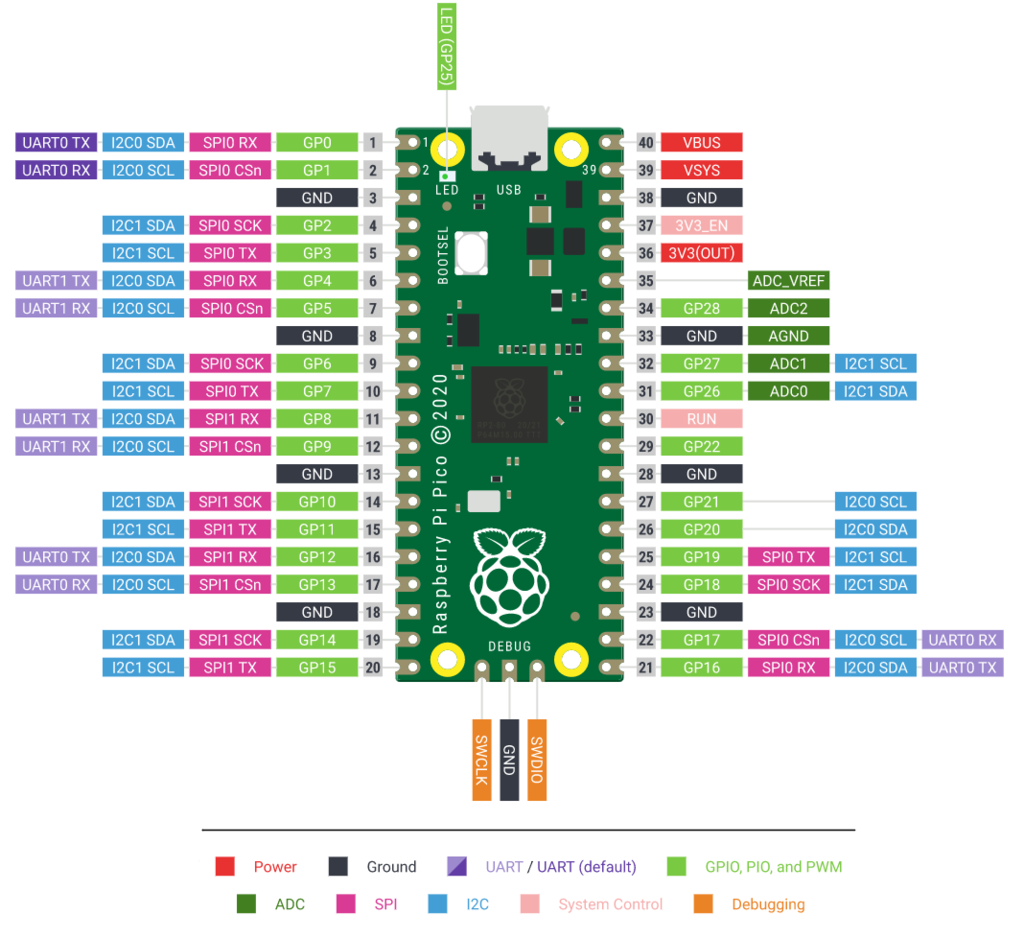
@Bodmer Thanks for the answer! Unfortunately that does not solve my proble. Is there anything else I can do to debug this problem? Just to be sure: the pins are referring to the GP pins (in green), so not the numbers in the gray squares, according to this picture?

Hi ,yanaukes, have you tried with MISO connected to nothing (on the air),even if the setup shows pin0?

@copyCATandpasteDOG Thanks for the suggestion. I tried disconnecting the MISO pin, but then I get no response at all from the touchscreen.

ryanaukes commented 1 year ago

Maybe it is helpfull. This is a part of the serial output of the "Test_Touch_Controller" sketch:

x: 0     y: 7936     z: 4863
x: 0     y: 7936     z: 4607
x: 0     y: 7936     z: 62463
x: 0     y: 7936     z: 65535
x: 0     y: 7936     z: 767
x: 0     y: 7936     z: 62463
x: 0     y: 7936     z: 2559
x: 2560     y: 7936     z: 64255
x: 0     y: 7936     z: 3583
x: 0     y: 7936     z: 65023
x: 0     y: 7936     z: 62719
x: 0     y: 7936     z: 62463
x: 0     y: 7936     z: 1535
x: 0     y: 7936     z: 511
x: 0     y: 7936     z: 62719
x: 0     y: 7936     z: 62207
x: 0     y: 7936     z: 1279
x: 0     y: 7936     z: 5119
x: 0     y: 7936     z: 62463
x: 0     y: 7936     z: 62719
x: 0     y: 7936     z: 3071
x: 0     y: 7936     z: 64767
x: 0     y: 7936     z: 3327
x: 0     y: 7936     z: 3071
x: 0     y: 7936     z: 62207
x: 0     y: 7936     z: 64767
x: 0     y: 7936     z: 4607
x: 0     y: 7936     z: 64255
x: 0     y: 7936     z: 511
x: 4864     y: 7936     z: 62463
x: 0     y: 7936     z: 1023
x: 0     y: 7936     z: 62463
x: 0     y: 7936     z: 1791
x: 0     y: 7936     z: 2815
x: 0     y: 7936     z: 767
x: 0     y: 7936     z: 62463
x: 0     y: 7936     z: 65535
x: 0     y: 7936     z: 62463
x: 0     y: 7936     z: 4607
x: 0     y: 7936     z: 3071
x: 0     y: 7936     z: 62719
x: 0     y: 7936     z: 64255
x: 0     y: 7936     z: 5631
x: 0     y: 7936     z: 62207
x: 7168     y: 7936     z: 62207
TangerineDreamer commented 1 year ago

ryanaukes wrote: "Thanks for the suggestion. I tried disconnecting the MISO pin, but then I get no response at all from the touchscreen."

of course TFT T_DO -> pin 0, even if MISO is disconnected

Bodmer commented 1 year ago

Which version of TFT_eSPI is being used?

Have you tried the suggested TFT_eTouch library?

TangerineDreamer commented 1 year ago

Maybe the pico has specifics pins that don't work in some cases, This setup works well for me:

// Stripped down User_Setup.h version for the Pico-Matrix-Touch-Keyboard //

#define ILI9341_DRIVER     

#define TFT_MISO  0
#define TFT_MOSI  3
#define TFT_SCLK  2
#define TFT_CS   20  // Chip select control pin
#define TFT_DC   22  // Data Command control pin
#define TFT_RST  21  // Reset pin (could connect to Arduino RESET pin)

#define TOUCH_CS 14     // Chip select pin (T_CS) of touch screen

#define LOAD_GLCD   // Font 1. Original Adafruit 8 pixel font needs ~1820 bytes in FLASH
#define LOAD_FONT2  // Font 2. Small 16 pixel high font, needs ~3534 bytes in FLASH, 96 characters
#define LOAD_FONT4  // Font 4. Medium 26 pixel high font, needs ~5848 bytes in FLASH, 96 characters
#define LOAD_FONT6  // Font 6. Large 48 pixel font, needs ~2666 bytes in FLASH, only characters 1234567890:-.apm
#define LOAD_FONT7  // Font 7. 7 segment 48 pixel font, needs ~2438 bytes in FLASH, only characters 1234567890:-.
#define LOAD_FONT8  // Font 8. Large 75 pixel font needs ~3256 bytes in FLASH, only characters 1234567890:-.
//#define LOAD_FONT8N // Font 8. Alternative to Font 8 above, slightly narrower, so 3 digits fit a 160 pixel TFT
#define LOAD_GFXFF  // FreeFonts. Include access to the 48 Adafruit_GFX free fonts FF1 to FF48 and custom fonts

// Comment out the #define below to stop the SPIFFS filing system and smooth font code being loaded
// this will save ~20kbytes of FLASH
#define SMOOTH_FONT

#define SPI_FREQUENCY  27000000

// Optional reduced SPI frequency for reading TFT
#define SPI_READ_FREQUENCY  20000000

// The XPT2046 requires a lower SPI clock rate of 2.5MHz so we define that here:
#define SPI_TOUCH_FREQUENCY  2500000

The sketch that works for me with pico: "Big keypad" from TFT e_spi (keypad) :

//Big keypad

#include "Arduino.h"
#include "LittleFS.h"

#include <SPI.h>
#include <TFT_eSPI.h>

// Name of the Touch calibration file
#define CALIBRATION_FILE "/TouchCalData2"

// Define our filesystem
#define FILESYSTEM LittleFS

// Set to tru if you want the calibration to run on each boot
#define REPEAT_CAL false

// Keypad start position, key sizes and spacing
#define KEY_W 95 // Key width
#define KEY_H 95 // Key height
#define KEY_SPACING_X 20 // X gap
#define KEY_SPACING_Y 10 // Y gap

#define KEY_X (KEY_W/2) + KEY_SPACING_X // X-axis centre of the first key
#define KEY_Y (KEY_H/2) + KEY_SPACING_Y // Y-axis centre of the first key

#define KEY_TEXTSIZE 3   // Font size multiplier

// Choose the font you are using
#define LABEL1_FONT &FreeSansOblique12pt7b // Key label font

// Adding a delay between keypressing to give our OS time to respond
uint8_t keydelay = 100;

// Create the screen object
TFT_eSPI tft = TFT_eSPI();

// Creating the labels for the buttons
// <name>[<number-of-lables>][<number-of-chars-per-label]
// The number of chars per label should include the termination \0.
char keyLabel[12][3] = {"1", "2", "3", "4", "5", "6", "7", "8", "9", "10", "11", "12"};

// Setting the colour for each button
// You can use the colours defined in TFT_eSPI.h
uint16_t keyColor[12] = {TFT_BLUE, TFT_RED, TFT_DARKCYAN, TFT_NAVY, 
                         TFT_MAROON, TFT_MAGENTA, TFT_ORANGE, TFT_SKYBLUE, 
                         TFT_PURPLE, TFT_ORANGE, TFT_PINK, TFT_DARKCYAN
                        };

// Create 12 'keys' to use later
TFT_eSPI_Button key[12];

void setup() {

  Serial.begin(115200);
  Serial.println("");

  // Initialise the TFT screen
  tft.init();

  // Set the rotation before we calibrate
  tft.setRotation(1);

  touch_calibrate();

  // Clear the screen
  tft.fillScreen(TFT_BLACK);

  // Begin the Keyboard

  // Draw the keys ( 3 times 4 loops to create 12)
  for (uint8_t row = 0; row < 3; row++) {   // 3 rows
    for (uint8_t col = 0; col < 4; col++) { // of 4 buttons

      uint8_t b = col + row * 4; // The button number is the column we are on added to the row we are on 
                                 // multiplied by the number of buttons per row. C++ uses the Order of operations
                                 // you are used to so first the row is multiplied by 4 and then the col is added.
                                 // The first button is 0.
                                 // Example. col = 2 (third column), row = 1 (second row), becomes: 1 * 4 = 4 --> 4 + 2 = 6. This is the 7th button.

      key[b].initButton(&tft, KEY_X + col * (KEY_W + KEY_SPACING_X),
                        KEY_Y + row * (KEY_H + KEY_SPACING_Y), // x, y, w, h, outline, fill, text
                        KEY_W, KEY_H, TFT_WHITE, keyColor[b], TFT_WHITE,
                        keyLabel[b], KEY_TEXTSIZE);
      key[b].drawButton();
    }
  }

}

void loop() {

  uint16_t t_x = 0, t_y = 0; // To store the touch coordinates

  // Pressed will be set true is there is a valid touch on the screen
  bool pressed = tft.getTouch(&t_x, &t_y);

  // Check if any key coordinate boxes contain the touch coordinates
  for (uint8_t b = 0; b < 12; b++) {
    if (pressed && key[b].contains(t_x, t_y)) {
      key[b].press(true);  // tell the button it is pressed
    } else {
      key[b].press(false);  // tell the button it is NOT pressed
    }
  }

  // Check if any key has changed state
  for (uint8_t b = 0; b < 12; b++) {

    if (key[b].justReleased()) key[b].drawButton(); // draw normal again

    if (key[b].justPressed()) 
    {
      key[b].drawButton(true);  // draw invert (background becomes text colour and text becomes background colour
      buttonpress(b); // Call the button press function and pass the button number
    }
  }

}

void buttonpress(int button)
{
  //Handle a button press. Buttons are 0 indexed, meaning that the first button is button 0.
  switch(button){
    case 0:     
     Serial.println("Button 1 pressed");   
     break;

    case 1:     
     Serial.println("Button 2 pressed");    
     break;

    case 2:     
     Serial.println("Button 3 pressed");     
     break;

    case 3:
     Serial.println("Button 4 pressed");
     break;

    case 4:
     Serial.println("Button 5 pressed");      
     break;

    case 5:
     Serial.println("Button 6 pressed");     
     break;

    case 6:
     Serial.println("Button 7 pressed");
    break;

    case 7:
     Serial.println("Button 8 pressed");     
     break;

    case 8:
     Serial.println("Button 9 pressed");   
     break;

    case 9:
     Serial.println("Button 10 pressed");     
     break;

    case 10:
     Serial.println("Button 11 pressed");     
     break;

    case 11:
     Serial.println("Button 12 pressed");     
     break;

  }
}

void touch_calibrate()
{
  uint16_t calData[5];
  uint8_t calDataOK = 0;

  // check file system exists
  if (!FILESYSTEM.begin()) {
    Serial.println("Formating file system");
    FILESYSTEM.format();
    FILESYSTEM.begin();
  }

  // check if calibration file exists and size is correct
  if (FILESYSTEM.exists(CALIBRATION_FILE)) {
    if (REPEAT_CAL)
    {
      // Delete if we want to re-calibrate
      FILESYSTEM.remove(CALIBRATION_FILE);
    }
    else
    {
      File f = FILESYSTEM.open(CALIBRATION_FILE, "r");
      if (f) {
        if (f.readBytes((char *)calData, 14) == 14)
          calDataOK = 1;
        f.close();
      }
    }
  }

  if (calDataOK && !REPEAT_CAL) {
    // calibration data valid
    tft.setTouch(calData);
  } else {
    // data not valid so recalibrate
    tft.fillScreen(TFT_BLACK);
    tft.setCursor(20, 0);
    tft.setTextFont(2);
    tft.setTextSize(1);
    tft.setTextColor(TFT_WHITE, TFT_BLACK);

    tft.println("Touch corners as indicated");

    tft.setTextFont(1);
    tft.println();

    if (REPEAT_CAL) {
      tft.setTextColor(TFT_RED, TFT_BLACK);
      tft.println("Set REPEAT_CAL to false to stop this running again!");
    }

    tft.calibrateTouch(calData, TFT_MAGENTA, TFT_BLACK, 15);

    tft.setTextColor(TFT_GREEN, TFT_BLACK);
    tft.println("Calibration complete!");

    // store data
    File f = FILESYSTEM.open(CALIBRATION_FILE, "w");
    if (f) {
      f.write((const unsigned char *)calData, 14);
      f.close();
    }
  }
}

Hope you'll find something to do with

ryanaukes commented 1 year ago

ryanaukes wrote: "Thanks for the suggestion. I tried disconnecting the MISO pin, but then I get no response at all from the touchscreen."

of course TFT T_DO -> pin 0, even if MISO is disconnected

I quickly tried that, but then I get the same results from the touch screen (high Z values). I will try the code you posted when I have some more time, thanks!

ryanaukes commented 1 year ago

Which version of TFT_eSPI is being used?

Have you tried the suggested TFT_eTouch library?

I am using version 2.5.0. Unfortunately I have not had the time to test the TFT_eTouch library. I will let you know if it works when I have time to test it.

ryanaukes commented 1 year ago

Today I had some time to do some more testing. It seems that the problem is related to the Arduino-mbed RP2040 core I am using. I installed the arduino-pico core by Earle Philhower using the board manager and now everything seems to work!

Thanks again for your help!

TangerineDreamer commented 1 year ago

Good news, i always thought you were using the Philhower library :)

Bodmer commented 1 year ago

Thanks for the update, glad to hear it is working now.

The TFT_eSPI library functions have worked with the Arduino-mbed RP2040 core in the past with the exception that the hardware PIO capabilities are not supported by the mbed core. I will investigate further, it may be the case that the mbed core has been updated and the compatibility has been lost or that a TFTeSPI library update has introduced an incompatibility.

The Philhower library is a better choice in most cases due to the enhanced capabilites and regular support updates.

Bodmer commented 7 months ago

I have tested this and it is working now with the latest Github master (not released yet).

I have not made any changes specific to this issue but maybe some other updates fixed this.