This might be a bit of a ramble because I am still trying to fill in all the blanks.
To remove complexity from the driver, we have opted to completely remove lower level controls from them. That means they will have no direct motor control or pnuematics control. To accomplish this successfully, we are going to have to model the entire system in state space and then have preset positions that the driver can request in button form.
First step is to identify the states, ins and outs of the system.
The states are represented here:
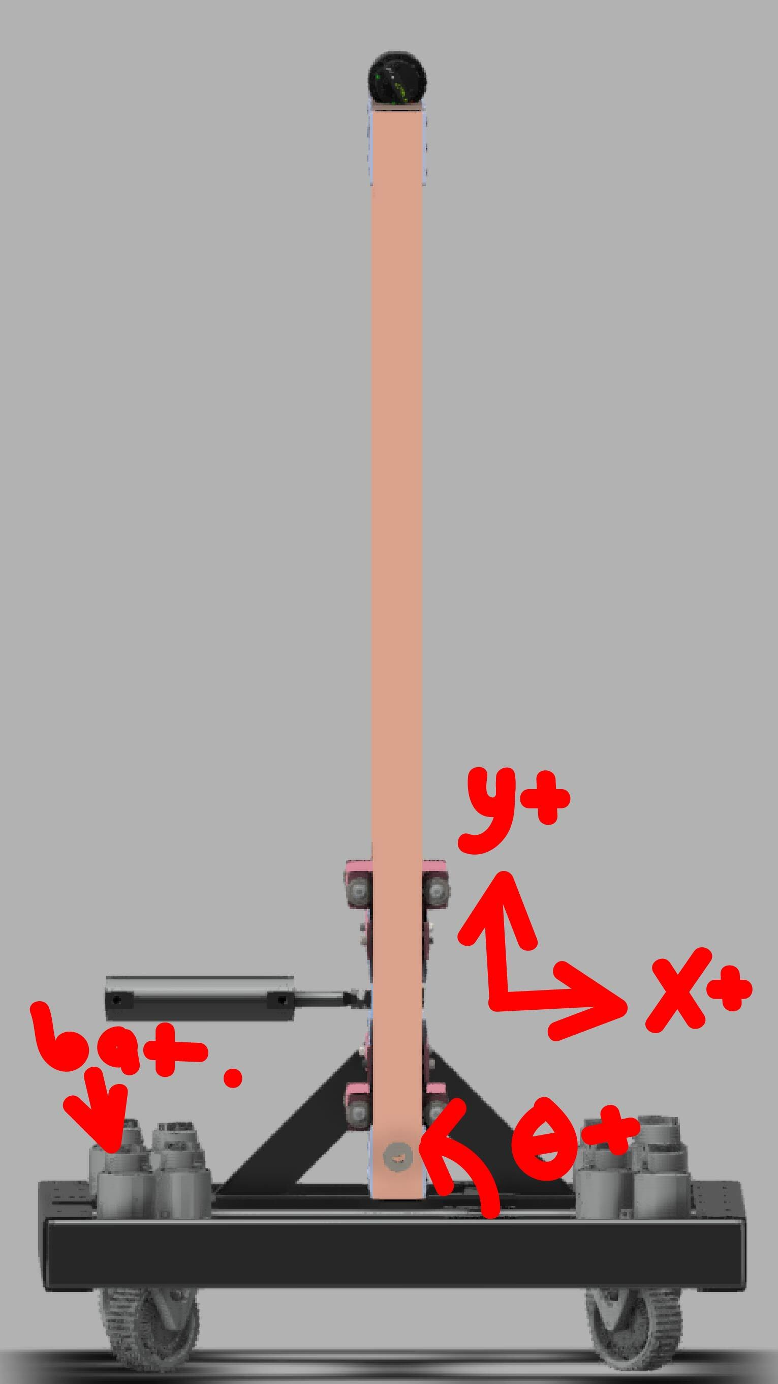
$x =$ the current x position in the robot's cartesian map
$Vx =$ the current velocity in x in the cartesian map
$E{mv} =$ the voltage into the elevator motor
$y =$ the current y position in the robot's cartesian map
$Vy =$ the current velocity in the y in the cartesian map
$T{mv} =$ the voltage in the telescoping arm motor
What about $\theta$ positioning?
We have decided to enumerate different $\theta$ positions. The actual $\theta$ of the elevator does not matter from a controller perspective, and neither do the enumerations. The driver should not have direct control of the elevator's selected enumeration because we can control that logic for them. From where we are right now, there would be three enumerated elevator $\theta s$:
Straight for middle nodes
Tilted negative to pick things off the floor.
What would a control request look like?
For example, if the driver wanted to place something on the top node, it would look like this at the top level request:
$x$ is equal to the requested position of the $x$ coordinate, in meters. This essentially represents the extension of the arm.
$y$ is equal to the requested position of the $y$ coordinate, in meters. This essentially represents the height of the arm.
$\theta_e$ is equal to the enumerated rotation of the elevator, and therefore the transformation of the end affector coordinate by a rotation matrix:
$$\Large
\begin{bmatrix}
cos{\theta} & -sin{\theta} \
sin{\theta} & cos{\theta}
\end{bmatrix}
\begin{bmatrix}
x \
y
\end{bmatrix}
$$
However, in actuality, there is a more complex underlying control request. There is also velocity control that is bundled with the
position requests.
$V_x$ is equal to the velocity the telescoping arm should be traveling.
$V_y$ is equal to the velocity the elevator should be traveling.
Another important part to mention is the control loop power one like this offers. You can apply an easing to the interpolation of the requested position vs the current position, and slow down the arm as it reaches the requested position.
Deriving a position
How we want to set this up is important. I would rather have transformations from an AprilTag to the low, middle and high nodes that are automatically translated into x,y,theta coords usable in the state space controllers. However, whenever we place something, we need to account for two rotations that intefere with our axises. The robot has to be given coordinates WITHOUT rotation, because the rotations will be given seperately. It is essentially like thinking the axises are rotated, but the coordinates themselves aren't because relatively they are just on an axis. First, let me define some terms. Whenever "absolute" is used, it's refering to field relative. Bottom right corner is 0,0 and X+ is facing towards the opposing alliance. Theta increases counterclockwise, as defined by general convention.
First, we need to take the absolute placing position coordinates and the absolute robot coordinates with a transformation to the axis of rotation for the entire elevator. The absolute placing position is $A_p$ and the absolute robot position is $A_r$. The transformation from robot absolute to axis of rotation absolute is $T$. This position is essentially the distances in xyz from the axis of rotation. We will call this the relative placing position, or $R_p$. We have to also subtract by claw distance, $c$, because we have a little room from the end of the arm to where the cone actually is, meaning the x-value we actually need to travel is shorter.
Like I said before, this returns the distances x,y,z from the axis of rotation of the elevator. Using those coordinates, we can start matching values. The robot Y should equal this distance Y because that equals the sideways alignment. If it is zero, there is no difference and therefore is aligned. x & z are next. Before we translate these values into coordinates for the elevator and telescoping arm, we MUST perform two rotation matrices to return this point that is going to be performed by an angled arm and elevator into something that is perpendicular to the floor or it's orthogonals. To do that, we are first going to rotate the point by the opposite of the rotation the elevator is currently at. That means if it is straight vertical, like it is when it is not engaged, it will be 0. Rotation is not necessary here. However, when it is rotated, $\phi$ will represent that rotation. To rotate this first axis, we do a rotation matrix of:
Next, we have to rotate the axis at the permanently rotated joint. To do this, we'll have to make the point of rotation the origin. Thankfully, since we corrected the rotation in the previous step, the x-axis is aligned, so we only have to move the origin of $z$. To do this, we'll just add $z^{\prime}$ to $z$ and then complete a rotation matrix by angle $\theta$ but negative, and then subtract $z$:
Finally we have to do a final transformation from the axis of rotation to the point of origin for the elevator. We will call this transformation $T_f$:
 davidmuchow
commented
1 year ago
davidmuchow
commented
1 year ago
This might be a bit of a ramble because I am still trying to fill in all the blanks.
To remove complexity from the driver, we have opted to completely remove lower level controls from them. That means they will have no direct motor control or pnuematics control. To accomplish this successfully, we are going to have to model the entire system in state space and then have preset positions that the driver can request in button form.
First step is to identify the states, ins and outs of the system.
The states are represented here:

$x =$ the current x position in the robot's cartesian map $Vx =$ the current velocity in x in the cartesian map $E{mv} =$ the voltage into the elevator motor $y =$ the current y position in the robot's cartesian map $Vy =$ the current velocity in the y in the cartesian map $T{mv} =$ the voltage in the telescoping arm motor
What about $\theta$ positioning?
We have decided to enumerate different $\theta$ positions. The actual $\theta$ of the elevator does not matter from a controller perspective, and neither do the enumerations. The driver should not have direct control of the elevator's selected enumeration because we can control that logic for them. From where we are right now, there would be three enumerated elevator $\theta s$:
What would a control request look like?
For example, if the driver wanted to place something on the top node, it would look like this at the top level request:
$x$ is equal to the requested position of the $x$ coordinate, in meters. This essentially represents the extension of the arm.
$y$ is equal to the requested position of the $y$ coordinate, in meters. This essentially represents the height of the arm.
$\theta_e$ is equal to the enumerated rotation of the elevator, and therefore the transformation of the end affector coordinate by a rotation matrix:
$$\Large \begin{bmatrix} cos{\theta} & -sin{\theta} \ sin{\theta} & cos{\theta} \end{bmatrix} \begin{bmatrix} x \ y \end{bmatrix} $$
This comes out to be equal to:
$\Large x^{\prime} = xcos{\theta} - ysin{\theta}$
$\Large y^{\prime} = xsin{\theta} + ycos{\theta}$
However, in actuality, there is a more complex underlying control request. There is also velocity control that is bundled with the position requests.
$V_x$ is equal to the velocity the telescoping arm should be traveling.
$V_y$ is equal to the velocity the elevator should be traveling.
Another important part to mention is the control loop power one like this offers. You can apply an easing to the interpolation of the requested position vs the current position, and slow down the arm as it reaches the requested position.
Deriving a position
How we want to set this up is important. I would rather have transformations from an AprilTag to the low, middle and high nodes that are automatically translated into x,y,theta coords usable in the state space controllers. However, whenever we place something, we need to account for two rotations that intefere with our axises. The robot has to be given coordinates WITHOUT rotation, because the rotations will be given seperately. It is essentially like thinking the axises are rotated, but the coordinates themselves aren't because relatively they are just on an axis. First, let me define some terms. Whenever "absolute" is used, it's refering to field relative. Bottom right corner is 0,0 and X+ is facing towards the opposing alliance. Theta increases counterclockwise, as defined by general convention.
$$\Large \begin{bmatrix} R{px} \ R{py} \ R{pz} \end{bmatrix} = ((\begin{bmatrix} A{rx} \ A{ry} \ A{rz} \end{bmatrix} \circ \begin{bmatrix} T_x \ T_y \ Tz \end{bmatrix}) - \begin{bmatrix} A{px} \ A{py} \ A{pz} \end{bmatrix}) - \begin{bmatrix} c \ 0 \ 0 \end{bmatrix}) $$
$$\Large \begin{bmatrix} x^{\prime} \ z^{\prime} \ \end{bmatrix} = \begin{bmatrix} cos{\phi} & -sin{\phi} \ sin{\phi} & cos{\phi} \end{bmatrix} \begin{bmatrix} x \ z \ \end{bmatrix} $$
$$\Large \begin{bmatrix} x^{\prime\prime} \ z^{\prime\prime} \ \end{bmatrix} = (\begin{bmatrix} cos{\theta} & -sin{\theta} \ sin{\theta} & cos{\theta} \end{bmatrix} \begin{bmatrix} x^{\prime} \ z^{\prime} + z \ \end{bmatrix}) - \begin{bmatrix} 0 \ z \ \end{bmatrix} $$
$$\Large \begin{bmatrix} X \ Z \ \end{bmatrix} = (\begin{bmatrix} x^{\prime\prime} \ z^{\prime\prime} \ \end{bmatrix} \circ \begin{bmatrix} T{fx} \ T{fz} \end{bmatrix} $$