CapableRobot / CapableRobot_USBHub_Firmware

https://www.crowdsupply.com/capable-robot-components/programmable-usb-hub
MIT License
9 stars 4 forks source link

USB Error - Broken Pipe (-EPIPE) during power measurement reads #4

Closed jynik closed 4 years ago

jynik commented 4 years ago

When running the script provided in #3, I've been encountering control IN requests failing with a URB status of "Broken Pipe" (-EPIPE). Below are the details in a Wireshark usbmon capture.

I'm curious to see if anyone experiences this as well, or if it's unique to my setup. Admittedly, I have quite a bit going that could be causing be trouble, including VMWare and nested hubs.

epipe

osterwood commented 4 years ago

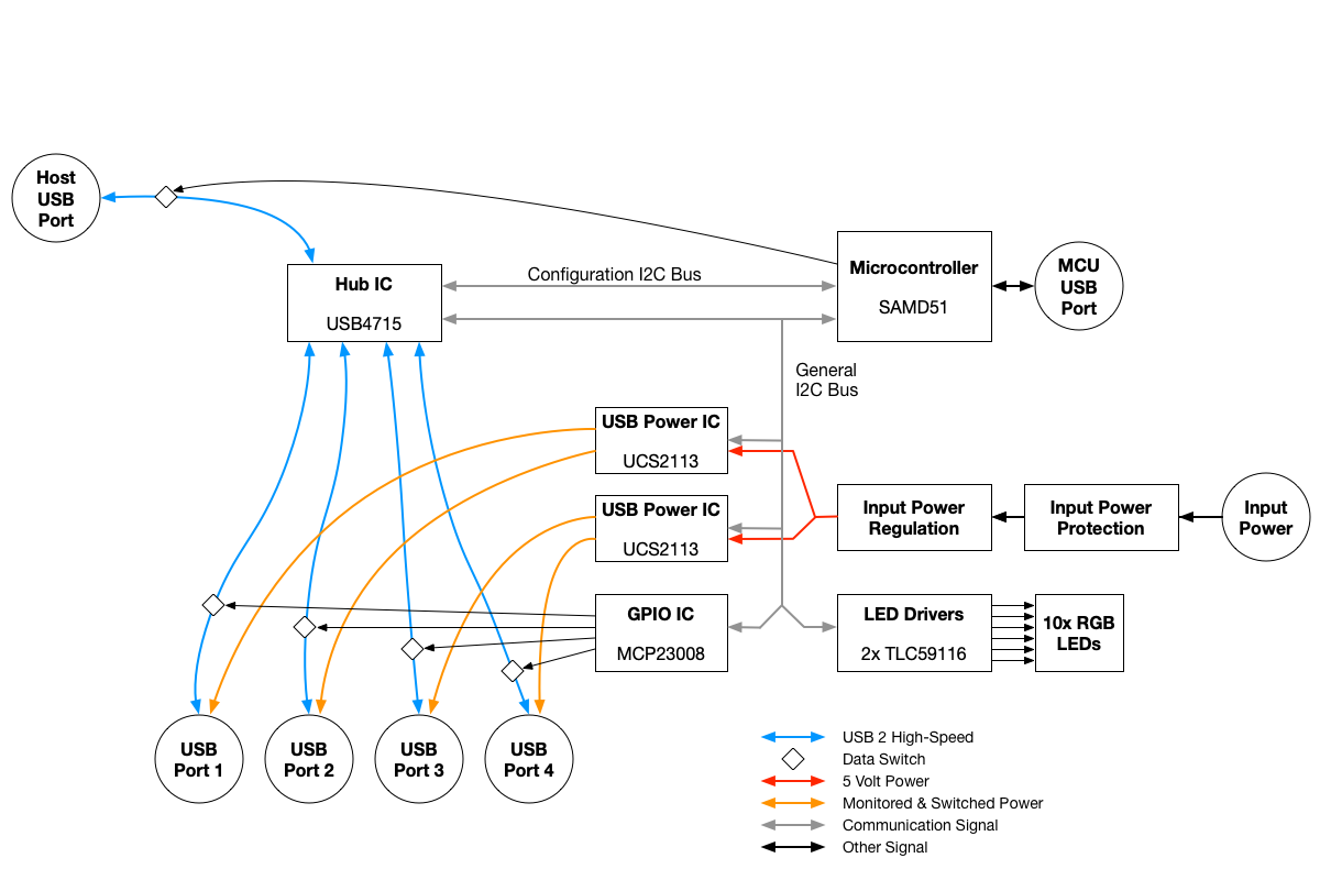
I am seeing this too. I think the issue is caused by a failed I2C transaction. While the monitoring script is running and reading the UCS2113 devices, the Hub MCU is reading from them too (at 10 Hz).

If the script and the Hub MCU start a read at the same time, the I2C read will fail and the drive just pops the error back to the caller. The firmware handles this multi-master conflict with a retry (see https://github.com/CapableRobot/CapableRobot_USBHub_Firmware/blob/6c7a4457039de24e87f729ee6df2c761de3fbe20/capablerobot_ucs2113.py#L46:L55)

After adding a time.sleep(0.01) prior to the power read in your script, the next test ran 5x longer than any previous running I had seen (with a rate of about 50/sec instead of 150/sec that I was seeing previously) -- due to reduced probability of contention.

Pausing the MCU I2C activity (via opening serial connection and entering the CircuitPython REPL), and running the script did not result in an error for over 10 minutes (after which I killed the script and wrote this).
jynik commented 4 years ago

Thanks for the quick follow-up and explanation - that makes sense. I need to get up to speed on CircuitPython and the Adafruit implementations a bit first, but will follow up with some proposed fixes if you don't beat me to it. :)

jynik commented 4 years ago

I see that the Adafruit BusDriver implementation acquires and releases a lock via __enter__ and __exit__.

I also note that the USB Hub firmware consistently accesses the bus devices using the with...as i2c: code pattern, thereby avoiding bus contention within the context of the CircuitPython code.

This leads me to suspect that the contention arises the handler for the USB IO Control handlers, which I imagine might be implemented within an ISR context, to further complicate matters, eh?

However, I'm not really certain where to find that code -- is this USB-to-I2C/SPI control interface presented as part of the underlying CircuitPython build? Definitely interested to dive into that a bit more.

osterwood commented 4 years ago

It's worse from a contention perspective than that -- the USB to I2C path doesn't hit the MCU at all. There are two masters on the I2C bus, the MCU (running the CircuitPython monitoring / LED update loop) and the USB4715, which has a 5th endpoint (likely an embedded 8051, but Microchip doesn't specify that) which implements various bridges (GPIO, UART, SPI, I2C). See the "General I2C Bus" in this image:

This post has more details about the internal architecture of the Hub: https://www.crowdsupply.com/capable-robot-components/programmable-usb-hub/updates/design-evolution-of-the-programmable-usb-hub

So, while the CircuitPython code can arbitrate I2C bus access for itself, it and the USB4715 cannot coordinate access -- hence the retry logic built into the MCU firmware.

Likely the "best" way to minimize end-user impact is for me to add similar retry logic in the host side driver, instead of requiring code outside the library to catch the pipe error and retry the I2C rear or write.

On an aside, the rational for this architecture was to minimize dependence on MCU for host-side monitoring and control. If the UCS2113 chip, GPIO expander, RGB LED drivers, etc were on the "Configuration I2C" bus, access to them from the host would involve the MCU acting as an I2C bridge. This would prevent the multi-master contention issue here, but would made it more difficult to modify MCU code for particular applications (as end users would have to maintain that host support bridge). As built right now, the MCU is responsible for USB4715 configuration upon boot & then it controls the status LEDs. No host-side functionality requires the MCU (assuming it has configured the USB4715 correctly).

jynik commented 4 years ago

Between your reply and the blog post, this makes perfect sense -- thank you for taking the time to explain!

I admittedly didn't realize the USB4715 was an additional bus master when I filed this. Given that this isn't really a firmware issue, please feel free to close this.

Just for the sake of future hw rev brainstorming (or for the bodge-wire-willing like myself)... I think I'm seeing USB4715 CONFIGSTRAP[2:1] set to Configuration 5, right? If so, are GPIO6 and GPIO11 available? I could envision doing an RTS/CTS-esque scheme between the host-side driver (via USB4751) and the SAMD51 firmware to negotiate control over the general I2C bus.

osterwood commented 4 years ago

Yes, configuration 5 is enabled through the strapping resistors. Those two GPIO are exposed on the JST-GH AUX connector (pins 3 & 4) and on the A4/A7 test pads on the bottom of the PCB. GPIO0 in the host side driver is pin 3 / GPIO6, GPIO1 in the host side driver is pin 4 / GPIO11.

https://github.com/CapableRobot/CapableRobot_USBHub_Driver/blob/master/capablerobot_usbhub/gpio.py

What you suggest is definitely possible with wire jumpers and modified firmware & host-side driver. It would reduce the need for I2C retries, but I think it would be difficult to completely eliminate the possibility of both side starting a transmission at the same time. Not sure how you would do a bi-direction (okay to send? yes, it is okay) between the two devices with just 2 wires.

osterwood commented 4 years ago

I've added retry logic to the host-side I2C bridge, which should resolve this issue. The MCU and Host Driver now both retry I2C transactions.

https://github.com/CapableRobot/CapableRobot_USBHub_Driver/commit/98964a5ef07632eaf257d9a98cf8690b20617845

jynik commented 4 years ago

@osterwood commented Yes, configuration 5 is enabled through the strapping resistors. Those two GPIO are exposed on the JST-GH AUX connector (pins 3 & 4) and on the A4/A7 test pads on the bottom of the PCB. GPIO0 in the host side driver is pin 3 / GPIO6, GPIO1 in the host side driver is pin 4 / GPIO11.

https://github.com/CapableRobot/CapableRobot_USBHub_Driver/blob/master/capablerobot_usbhub/gpio.py

What you suggest is definitely possible with wire jumpers and modified firmware & host-side driver. It would reduce the need for I2C retries, but I think it would be difficult to completely eliminate the possibility of both side starting a transmission at the same time. Not sure how you would do a bi-direction (okay to send? yes, it is okay) between the two devices with just 2 wires.

It's still a rough idea, but here's a quick overview. Happy to discuss further (e.g., sketch out a more complete state flow) if this is something you'd be interested in pursuing -- even if only as a "proposal and PR welcome" back-burner item. Not sure if it's worth losing those 2 GPIO pins over, if there are other plans for them.

I'd envision a scheme with a HOST_REQ (host requests bus ownership) and MCU_REL (MCU has relinquished control) pair of signals, whose directions are shown below.

Signal Name Host SAMD51
HOST_REQ Output Input
MCU_REL Input Output

The SAMD51 would "own" the bus and but give priority to the Host when it (the Host) requests to take bus ownership by asserting HOST_REQ. When the SAMD51 sees this request line asserted, it would acknowledge the request and signal that it has relinquished ownership of the bus by asserting MCU_REL.

Once the host is in the state (HOST_REQ: Asserted, MCU_REL: Asserted), it could then proceed to perform one or more I2C bus transactions. When it is done, it de-asserts HOST_REQ.

When the SAMD51 wishes to perform a bus transaction, it would only do so when it first observes that (HOST_REQ=Deasserted, MCU_REL=Deasserted). (Perhaps a patch to the Adafruit driver's __enter__ might be a reasonable way to achieve this, without placing too much burden on folks wishing to explore and customize their firmware?)

It is reasonable to assume that a host program could crash while holding HOST_REQ asserted, effectively starving the MCU of its ability to use the bus. I suppose the MCU could deduce that this is the case after HOST_REQ has been asserted for more then some time period, and then proceed to ignore it until it sees HOST_REQ de-asserted, which presumably would occur early in the driver-side initialization when the USBHub handle is being created. This would also place an upper bound on how many back-to-back bus transactions the driver could perform before giving the MCU a chance to have access to the bus.

As you noted, this would require modifications to hardware, firmware, and the host driver. In order to support both the current and future/modded hardware, perhaps some version info (e.g. minor revision #) or capabilities flags stored in the EEPROM could be used to denote whether this flow is supported? Both the updated driver and firmware would be responsible for checking this information before entering this flow.

I've left "assert" and "de-assert" ambiguous as to their values here, as there may also be some wiggle room available based upon the pull-up/down options of GPIO pins, such that the system defaults to its current retry-based behavior if the aforementioned signals are not connected.