Open Darthpbal opened 7 years ago
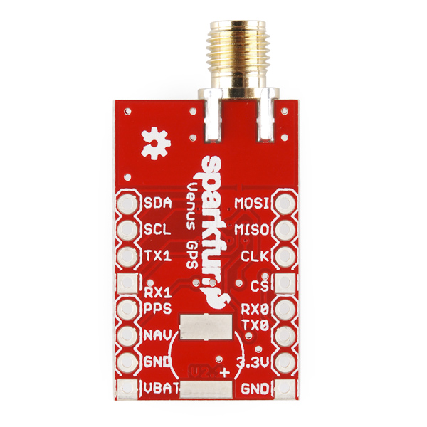
This board is implemented using a long weather proof external high gain antenna
the board is based on a chip called Venus638FLPx
this hookup guide shows the code implemented for the gps.
it appears to be a simple char by char reading of the uart data through software serial into a char array buffer and terminates with a null. Then he uses a function that takes in a small buffer and the field number in the gps string you want based on commas, which the mechanism implemented is also very similar to my column extracting program I made on a desktop for extracting lat/long/altitude and stuff from a csv file.
this board is a 3.3V only board. So don't have it connected while uploading to a 5V controller like an uno.
Also, since I'm only listening in on this board and never sending it commands, I can just rely on the fact that the 3.3V level is past the high threshold for 5V TTL logic.
hazzah
The board operates pretty much in the same way the ultimate gps board from adafruit so far in my demo. The sensor spits out sets of data in the group below. Then some helper functions are used for retrieving a desired field from the sentence. I'm gonna try to see if I can port my previously made gps program over since I know that it works passively alongside other devices just fine. Then I need to change the speed settings to at least 15 HZ
$GPGSA,A,3,02,24,12,06,19,05,17,29,,,,,1.6,1.0,1.2*36
$GPGSV,3,1,09,02,84,265,45,12,67,329,47,06,45,042,31,24,35,234,36*76
$GPGSV,3,2,09,19,27,065,33,25,23,318,29,05,23,163,40,17,12,076,24*7E
$GPGSV,3,3,09,29,06,276,23*4F
$GPRMC,000859.775,A,3326.5290,N,11224.3104,W,000.0,000.0,240517,,,A*70
$GPVTG,000.0,T,,M,000.0,N,000.0,K,A*0D
$GPGGA,000900.775,3326.5290,N,11224.3104,W,1,09,0.9,295.0,M,-28.3,M,,0000*60
my ultimate gps port totally works perfectly after changing all the reading functions to software serial!
The benefits this provides is basically my functions are asynchronous with respect to the GPS sensor. What I mean, is that it doesn't matter if you ignore the sensor for arbitrary amounts of time, the function can be called anywhere. This code basically waits and reads the GPS NMEA tag checks it against a preferred tag and either tosses it if mismatched and then wait for the next tag, or if the tag is a match, then all of the next set of data is read into a variable until the next newline is seen. This means the entire GGA sentence (lat/long/alt) can be recorded will all contextual data.
I rather prefer recording everything I can get from a sensor unless I'm really hitting memory limits.
Another benefit of my previously made code that isn't implemented in the demo code is a timeout function which would be necessary for detecting whether or not the GPS is disconnected from faulty fabrication like a disconnected wire or getting ESD fried (error tolerant). The desired tag, sentence size, and timeout all can be changed to be globals to make changing settings or wires super easy.
connect the + or 3.3V pin and - symbols to 3.3V and gnd respectively, and then TX to a software serial pin on the controller.
DO NOT use hardware serial pins on controller to avoid the reupload conflict and to avoid overvoltage of the GPS board
By the looks of it, there are several things I can do to squeeze as much speed as I can out of this baby.
First, of course is the configuration to 20Hz. According to the documentation it needs to also change UART speed to 115200 in order to do that, which will shorten how much time each data burst is. Then, the specific GPS messages we receive can be configured I believe to the point where we can configure it to ONLY send us what we want, no GPS code filtering needed on out end, only logging. This would basically take the output referenced above, showing 7 sentence bursts, and make it so instead of having that be the repeating pattern, it only sends out GGA over and over, which would cut transmission period to 1/7th of what it originally was.
make sure to update the flash and sram when trying to make changes permanent. Don't make any changes permanent until I've verified they're working correctly first
it looks like the configuration of the gps is done through a companion program that skytraq, the makers of the chip provide. However, the hardware configuration to establish communication with the chip is not defined.
What I'm assuming, is that I'm supposed to program an arduino as a serial passthrough, to communicate directly with the device. If this is the case, and if this is sending as simple of commands as I think, I believe I should be able to code up a way to configure this device in a lot of different ways autonomously. Which could be nice in some circumstances.
best friggin guide I've seen available for actually defining the hardware interface between the board and the configuration software. It's noted in the "support tips" tab at the bottom of the product page for the version of this board with a JST connector on it.
Hmm... The page where this guide is says it was updated yesterday. And I'm not sure if that means the support documents for this is fickle. Certainly there is vague documentation that isn't really at a lower level. So to safeguard this info, I'll paste it here.
How to use the logger functions First, you must use the SkyTraq software we have on the product page. 1- Connect a LiPo battery to the JST connector, OR an external 3.3 volt DC power supply. (Don’t use a 3.3 volt FTDI breakout for power, it can’t supply enough current. The Beefy 3 should be OK) 2- Download and install the SkyTraq 0.4.833 software from the product page. 3- Connect a 3.3 volt FTDI breakout (or other 3.3 volt USB to serial converter.) to the GND, RX and TX pins on the Venus GPS. 4- Start the SkyTraq software, select the COM port your FTDI breakout is on. Set the baud rate for 115200 and then click the “Connect” button. You should start seeing NMEA data scroll by in the message window. 5- Go to the “DataLog” menu at the top of your screen and select “Log Configure.” Change any options you want to. I find that the defaults work well. 6- At the bottom of the Log Configure Control window, select “Enable” for the “DataLog:” option, then click the button labeled “Settings”You should see “Log Configure Control Successful” appear in the Response window. 7- If you want to start with a fresh empty log, go back to the “DataLog” menu and select “Log Clear.” You should see “Log Clear Control Successful” in the Response window. 8- At this point, your Venus is logging data to it’s onboard memory. Take the GPS with you on a nice hike, or a short drive around the block. To retrieve that data follow the next steps. 9- Reconnect your Venus to a computer with a FTDI cable like you did before, then follow step 4 to get SkyTraq ready to download new data. 10- Go to the “DataLog” menu and select “Log Read Batch.” The software will prompt you to save the accumulated data to a file on your computer. Click save to do that. 11- At this point, you have downloaded a compressed version of your stored GPS data to your computer. In order to convert that to use able data, you need to do one more step. 12- To convert that data file, go back to the “DataLog” menu and select “Log Decompess.” The SkyTraq software will ask for the file you just downloaded. Select that file, then click on save. A window saying “Decompress is completed!” should appear. Click OK. 13- In the same folder you downloaded the GPS data, you will now find three new files. a .logg file that contains human readable positional data, a .nmea file that has raw NMEA GPS data in it, and a .kml file that can be loaded up in Google earth showing your journey.
I've been able to configure the venus gps actually quite easily using the skytraq software. It's quite well made, however it's only downfall is a poor definition of a preferred hardware connection or even any example suggestions circuits other than just saying "connect it to an ftdi"... umm okay, no reset signals? waaaaat?
I achieved a hardware connection by setting up a bidirectional level shifter to transmit to and from the gps to my UNO board. Then used the serial passthrough example built into arduino, but instead of using the Seral1, I used a SoftwareSerial port on pins 10 & 11 and simply tried to match the baud rates. Then open up the companion software using windows (unfortunately) and it autodetects the serial port if the arduino IDE isn't connected.
The logic level converter is basically for safety not having to disconnect anything in between uploads since the gps is 3V and also since I want to preserve the signal quality of the board. Unfortunately it looks like that may not be enough at the super high speed 115200 baud since I saw consistent degeneration of the characters streaming from the arduino.
This is basically just for setting up a direct UART to USB connection to the software.
since the software is made so easily it makes changing the settings for the GPS both temporarily until the next power cycle as well as permanently in flash a breeze. This also means I have a point where I can measure the serial data being sent to configure the gps to set up a method for configuring the gps in setup without needing to permanently change it, allowing easy use for the next people using this board. It also helps avoid the possibility of changing to some communication setting combination that doesn't work, you at least always have a known default it always refers back to.
how to get the viewer software working in linux https://ubuntuforums.org/showthread.php?t=1335098
I was worried that it might be possible to configure the device into a conflicting state since is says it does certain interval update speeds only at certain other baud rates. If this works the way I think, that would mean if at lower update intervals and baud rates, one w ould have to update baud rate before updating reporting interval. Basically, the lower the update rate, the more baud rates it's compatible with. Higher update rates are only compatible with higher baud rates.
Because of this order of operations (that I assumed was the only safe way) I was never actually able to hit the golden fastest speed by reducing the kinds of NMEA messages that appear, and increasing baud rate and update interval. I wasn't able to do this because I would update the baud rate to 115200, the only baud rate compatible with 20Hz update rate. But that baud rate had a consistent breakdown in signal quality such that I wasn't able to read or send correct characters and needed to rely on the fact that I deliberately never changed the flash memory so that if the board became unusable from corrupt settings, I could power off and on again to get a working device back.
That's all sunshine and farts until I accidentally broke the order of operations. And I know i didn't really have a reason for believing this would corrupt the board, but it appears to have done just that.
The board is sending nothing but garbage data to the arduino reading it, even at the lowest speeds. So I know it isn't signal degredation. And I've test read at every single baud rate I have available because I tried reading using the original baud rate but it didn't work.
I'm thinking I need a factory reset. This page seems to have something that sounds like what I need.
Good news And bad news.
Bad news is that documentation on how to put the board in ROM mode and then update the firmware when the serial port communication is corrupted is pretty weak. Reasearch into the rom mode operation for sister venus/skytraq gps chips shows that I need to pull the boot mode pin high or low, but the schematic for the GPS device says that pin is not connected. So I'm confused...
Good news is I didn't power the device at all for a while and just now tried it again, and it looks like it's responding again! Configurable and everything. I love it when problems solve themselves.
Im also testing with a new setup. I'm now both connecting an FTDI for more direct communication with the gps board as well as feeding the data into the arduino to see how it sees things. PROGRESS! I found that when setting the device to baud rate 115200 I saw the data come in through the FTDI just fine, but when the arduino reads the data, it's corrupted. So that means 115200 is just too fast/noisy for the arduino uno in this configuration. I wonder if a faster cpu would read this data better.
Thanks to the new test circuit, I'm able to view the arduino perspective of the GPS as well as interface with it in a more direct way using the direct FTDI board through a level shifter.
The additional benefit of this setup is I'm also able to switch the wire for the software serial pin from the GPS tx to the FTDI tx so that I can see the commands actually being sent to the GPS device as well as maybe spot an acknowledge byte as well. I've sucessfully viewed the configuration sentences and have also reset the system to it's factory defaults to avoid corruption issues.
Now that I know the configuration sentence formats and how to actually send them to the gps (serial passthrough example demonstrates this) I can now write a library for configuring the board using only sram in a setup procedure to avoid corruption and still get the desired settings every time the system starts up
Roller coaster ride nearing a close.
Basically the development I've been doing the last few days is just coding up a library for the Venus GPS.
I wanted a library because of the different configurations that can be made on the board, along with the possible danger coming from any permanent setting changes in the accidental incident where incompatible settings are changed.
Another benefit is the idea that we may want to change the way our GPS data is being reported later. And having a decent way to work with the sensor quickly and without complicated crap to just simply get a lat/long pair. We can change the settings however.
Because of this, I basically wanted something that could be configured in a setup loop, and then run in a couple lines in english without ignoring the GPS for an unknown amount of time being a problem, and with the ability to auto update the arduino to GPS baud rate automatically when the configuration is made. and everything.
Basically, I've run into a bunch of memory issues because I was more or less reusing some previously used GPS code that was made for a different context. This was the first GPS library I've made, and the code needed to be different enough that I had to redevelop a parsing algorithm for it.
But after sweat and tears, the current system runs at 9600 baud at 1Hz update rate with absolutely no dataloss between changing settings and no restarting issues from memory problems.
All that is made now with a parser as well, and I just have the breakout board configuration code left, but as is, the system would work for launch if we just permanently changed the settings.
Not to tute my own horn, but I just loaded up the adafruit GPS library and compiled it for an UNO against my library so far with parsing . Firstly, my version is effing readable. Theirs uses a lot of hex and stuff that isn't obvious in high level meaning aside from the actual print statements. like "GPS.lat". Parsing example compiles to 35% of total UNO memory space and 45% of dynamic memory.
Mine reads data as you ask for it rather than constantly doing calculations in the background when you're not even trying to check it. The user functions are english readable. You might not be able to get latitude using a GPS.lat syntax, but grabbing that field is pretty easy assuming the use knows what GPS sentence they want and what data they wanna fetch from it if they even wanna do that extraction. Not even required, because the user can also just log every sentence. The beauty is also the fact that all the filters and everything can be turned off and basically turn the library into a serial passthrough.
currently working on gps
there appears to be some kind of error that is making the GPS library filter functions not work correctly.
I think this problem came up when I had some kind of memory overflow by storing data in an index position greater than the character arrays size. However I'm doing this with strings. So I'd think memory management is better. But here we are.