 amcewen
commented
3 years ago
amcewen
commented
3 years ago @kayharvey and I have investigating it and making a start on cleaning today.
I think we've got most of the cleaning done - the keys are drying, and need their rollers oiling before they're reassembled. Next steps we think are...
- Reassemble it all
- Check the springs, particularly on the receiver "print head" and the one on end transmitter rail which is currently unhooked
- Check over the wiring with a meter (there's a wiring diagram at the end of Chapter 2 in the book)
- Possibly clean the carriage (we've only worked on the transmitter and receiver units today)
- Work out how we power it - the motor is marked as DC, but bits of the manual imply that you can maybe run them on AC and Dean at Western Approaches said they'd just stuck a plug on one a while back.
- It feels like it'll make sense to run it through @magman2112's mains isolator unit, so finding out how that works would be handy
- Fire it up and see what happens when it's running!
- Find a new ribbon for it
 pkharvey
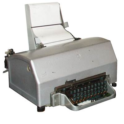
 Sean-anotherone
 9600
9600 magman2112
So, Western Approaches have a bunch of teleprinters from when they were operational in the Second World War. They've lent us (might well be long-term loan or donation if we want one) to see if we can get it up and running and talking to something across the Internet... It's a Creed Model 7B:
@magman2112 has bought a book about them with a bunch of details in it - chapter 2 of that is also available online, and there's a Post Office manual for it