Closed pigiit closed 2 years ago
Hi Pierluigi,
You are very quick in seeing this functionality :smile: I just did the sideboard implementation and next is the main board. The main board is not yet prepared to accept the data. I hope to do it soon. My intention is to have dual input support, so I can control my Hovercar with both pedals on ADC and RC transmitter via sideboard.
So it is clear why you have the 3 beeps. It is not yet ready. I will let you know when is done :wink:
And yes the blue board version is indeed a bit more difficult since the pins are not routed. But is doable. Meanwhile you can give a try with DEBUG variant on sideboard, and a serial terminal to check that is able to get data from Transmitter. It should read 2 channels and the switches (which i intend to use for switching modes)
Ok thanks, now it is clear why it was not working and of course congratulation for the excellent work and thanks for sharing it!
I tried also do add the missing code by myself, something like cmd1=sideboard_L.cmd1 in util.c, but need to familiarize with the existing code first, I think it's much better to wait for next version :-)
I would like to control the hoverboard with Arduino using one of the serial ports, but having the option to take control of the motors using one of the switches/channels of the remote control
Last question, is it possible to add a control mode using "steps" for L and R motors?
Thanks again Pierluigi
So you want to control with both UARTs, one connected to Arduino and one to sideboard RC?
And what do mean by "steps" mode?
I would like to have an autonomous control (arduino and sensors on the available serial 3 port is one of the options) + a manual control that can be enabled from one of the the remote control switches. This can me done already using an arduino with 2 serial ports and connecting both receiver and hoverboard to arduino (this was my configuration) but the receiver on the sideboard is a much more efficient option, leaving more resources on the mcu (arduino in this case) used for the autonomous control
About the steps, I mean to use the motor like a stepper motor, commanding to move the motor 1 step only (may be an arc of 3 magnets or 1 phase looking at the motor design of the hoverboard) and then activate the brake. The delay between commands can be proportional to the movement on the joystick...just an idea. Having the hall sensors it should be possible
And how do you plan to connect both the Arduino and the sideboard with receiver to the mainboard? I guess Arduino to UART3 and sideboard to UART2 of the mainboard correct?
Regarding the stepper mode, i have to think, i am not sure how easy or difficult it is to implement.
yes, one sideboard only that also gives gyro info on serial 2 and arduino on serial 3 because in 5v tolerant
to be honest I do not have already a project, just trying to explore how powerful can be an hoverboard with all those options available to build an autonomous vehicle.
if you program the board with a not too strong brake and try to turn the wheel by hand, you can feel that there is a kind of stable position that the controller tries to keep and if you are strong enough you can pass that point and fall in the next one, that's what I mean for a step. A brushless controller with no hall sensors should detect the movement with currents in the other phases I guess, but having the sensors it should be easy and possible also at very low speed...but of course you are the expert :-)
just trying to give an input to expand even more the possible applications of your great firmware
Hi Emanuel,
in order to have siteboard2 with iBus receiver and arduino with basic test software you provided, I tried wit following configuration in the usart mode:
// #define SIDEBOARD_SERIAL_USART2 0 // #define CONTROL_SERIAL_USART2 0 // left sensor board cable, disable if ADC or PPM is used! For Arduino control check the hoverSerial.ino // #define FEEDBACK_SERIAL_USART2 // left sensor board cable, disable if ADC or PPM is used!
// #define SIDEBOARD_SERIAL_USART3 0 // #define CONTROL_SERIAL_USART3 0 // right sensor board cable. Number indicates priority for dual-input. Disable if I2C (nunchuk or lcd) is used! For Arduino control check the hoverSerial.ino
#define FLASH_WRITE_KEY 0x1102 // Flash memory writing key. Change this key to ignore the input calibrations from the flash memory and use the ones in config.h
#define SIDEBOARD_SERIAL_USART2 0 // left sideboard
#define SIDEBOARD_SERIAL_USART3 1 // right sideboard
#define AUX_INPUT1 3, -1000, 0, 1000, 0 // TYPE, MIN, MID, MAX, DEADBAND. See INPUT FORMAT section
#define AUX_INPUT2 3, -1000, 0, 1000, 0 // TYPE, MIN, MID, MAX, DEADBAND. See INPUT FORMAT section
motors not enabled, 3 beeps as error code, but receiver's switches works even if cannot switch on second input it seems to me the serial protocol sent from arduino is not ok for serial 3
with the following change
#define **_CONTROL_SERIAL_USART3_** 1 // right sideboard
I can spin the motors but only using the iBus receiver on sideboard2 and all the switches on the radio are not working... whatàs the right configuration in this specific case?
Thanks!
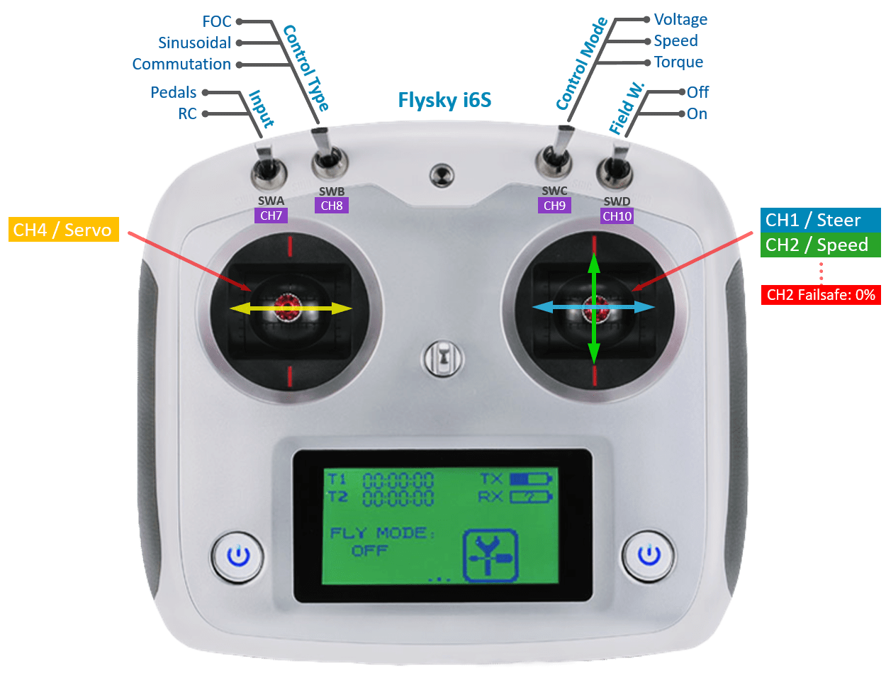
About the RC switches I would like to add a detail that can help, Swa, b, c, d are mapped on the channels ch7,8,9,10 on the iBus protocol
sorry..
with #define CONTROL_SERIAL_USART3 1 // right sideboard
motors moves according with arduino commands, receiver is not working
Hi all,
the following configuration works, even if after a while, trying to switch from serial3 and serial2 the control is lost and need to reset both arduino and hoverboard
#define FLASH_WRITE_KEY 0x1102
#define SIDEBOARD_SERIAL_USART2 1 // left sideboard
#define CONTROL_SERIAL_USART3 0 // right sideboard
hope there is a way to have a more stable system
Thanks
I can spin the motors but only using the iBus receiver on sideboard2 and all the switches on the radio are not working...
There was a bug. Can you use last commit? It should be fixed. Sorry for late reply.
@pigiit For you setting I recommend:
Just uncomment #define DUAL_INPUTS
for that variant. Should normally work.
Thanks Emanuel, all ok now! Great improvement. I noted a couple of minor issues (maybe):
Thanks!
Thanks for the input @pigiit
if one of the inputs is not available one main board starts it is exlcuded until next reboot (I mean first you need to start the input sorces and then overboard)
For this one I prefer not to exclude the input if it is not available because let me give you an example. For my Hovercar, I will turn it on without receiver being powered at all and in the middle of operation I will turn the receiver on to control it via RC transmitter. So, here I want to avoid a power on/off cycle if the non existing input is excluded.
the other switches are always beeping when position changes, new modes are correectly activated but you need to movbe the switch to new desired mode and then back to default position in order to stop the sound, a bit confusing..
Are they still beeping? It should be fixed in my last last commit. I tested it and all switches on this transmitter work properly. Can you confirm?
Ok I'll try again and let you know No sure if it's what you mean, but at the moment if one input is not available when the main board starts, it's not used untill next reboot
Not available you mean not connected? Because it should allow you to select it once it is connected. No need for a reboot normally.
I just did some tests:
downloaded and installed last hoverboard firmware version (I only changed it to add channels 3,4,5,6 in the sideboard to mainboard protocol, this to reflect the firmware change on sideboard I did to have 6 ch and not 2 ch and avoid to reflash also the sideboard with original firmawere)
arduino is using your original test program (just changed the serial ports configuration in order to use it on arduino mega version I have)
All is ok when when the 2 inputs are not working together (note: input switch never gives any beep feedback for all the tests)
Arduino powered off -> Remote radio is working good and also the switches are ok
as soos as Arduino starts the radio stops, no controll on the wheels, no beeps/control of the switches
disconnect Arduino and R/C restarts again...
the switch on channel 7 for dual input seems not controlling any switch between inputs
Hope this helps the troubleshooting
Forgot to mention the config
// ############################ VARIANT_USART SETTINGS ############################
// #define SIDEBOARD_SERIAL_USART2 0 // #define CONTROL_SERIAL_USART2 0 // left sensor board cable, disable if ADC or PPM is used! For Arduino control check the hoverSerial.ino
// #define SIDEBOARD_SERIAL_USART3 0 // #define CONTROL_SERIAL_USART3 1 // right sensor board cable. Number indicates priority for dual-input. Disable if I2C (nunchuk or lcd) is used! For Arduino control check the hoverSerial.ino
#define FLASH_WRITE_KEY 0x1102 // Flash memory writing key. Change this key to ignore the input calibrations from the flash memory and use the ones in config.h
#define SIDEBOARD_SERIAL_USART2 0 // left sideboard
#define CONTROL_SERIAL_USART3 1 // right sideboard
#define AUX_INPUT1 3, -1000, 0, 1000, 0 // TYPE, MIN, MID, MAX, DEADBAND. See INPUT FORMAT section
#define AUX_INPUT2 3, -1000, 0, 1000, 0 // TYPE, MIN, MID, MAX, DEADBAND. See INPUT FORMAT section
#define FLASH_WRITE_KEY 0x1002 // Flash memory writing key. Change this key to ignore the input calibrations from the flash memory and use the ones in config.h
// #define SUPPORT_BUTTONS_LEFT // use left sensor board cable for button inputs. Disable DEBUG_SERIAL_USART2! // #define SUPPORT_BUTTONS_RIGHT // use right sensor board cable for button inputs. Disable DEBUG_SERIAL_USART3!
I only changed it to add channels 3,4,5,6 in the sideboard
Where did you do this? In the Sideboard code (see below) Ch1 = steering
Ch2 = speed
Ch7-10 = {SWA, SWB, SWC, SWD}
.
I just checked the code for your setting VARIANT_UART with DUAL_INPUTS and I didn't see anything strange. Can you give more details on how did you change the Sideboard code? And what transmitter are you using?
@pigiit I think I see the error now in your config.h
#define SIDEBOARD_SERIAL_USART2 0 // left sideboard
#define CONTROL_SERIAL_USART3 1 // right sideboard
The Sideboard is not forseen to operate in Priority 0 (as Primary input). You should change it to 1
. You can also use it as you have but it will not do the Input switching mechanism unless you update some things in util.c
. i think the easiest is to update to:
#define SIDEBOARD_SERIAL_USART2 1 // left sideboard
#define CONTROL_SERIAL_USART3 0 // right UART
I'll try that, thanks
about the change done:
util.h and util.c
typedef struct{
uint16_t start;
int16_t pitch; // Angle
int16_t dPitch; // Angle derivative
int16_t cmd1; // RC Channel 1
int16_t cmd2; // RC Channel 2
int16_t cmd3; // RC Channel 3
int16_t cmd4; // RC Channel 4
int16_t cmd5; // RC Channel 5
int16_t cmd6; // RC Channel 6
uint16_t sensors; // RC Switches and Optical sideboard sensors
uint16_t checksum;
} SerialSideboard;
void usart_process_sideboard(SerialSideboard Sideboard_in, SerialSideboard Sideboard_out, uint8_t usart_idx) { uint16_t checksum; if (Sideboard_in->start == SERIAL_START_FRAME) { checksum = (uint16_t)(Sideboard_in->start ^ Sideboard_in->pitch ^ Sideboard_in->dPitch ^ Sideboard_in->cmd1 ^ Sideboard_in->cmd2 ^ Sideboard_in->cmd3 ^ Sideboard_in->cmd4 ^ Sideboard_in->cmd5 ^ Sideboard_in->cmd6 ^ Sideboard_in->sensors); if (Sideboard_in->checksum == checksum) { Sideboard_out = Sideboard_in; if (usart_idx == 2) { // Sideboard USART2
timeoutCntSerial_L = 0; // Reset timeout counter
timeoutFlgSerial_L = 0; // Clear timeout flag
#endif
} else if (usart_idx == 3) { // Sideboard USART3
#ifdef SIDEBOARD_SERIAL_USART3
timeoutCntSerial_R = 0; // Reset timeout counter
timeoutFlgSerial_R = 0; // Clear timeout flag
#endif
}
}
} }
a similar change on sideboard firmware
typedef struct{ uint16_t start; int16_t pitch; // Angle int16_t dPitch; // Angle derivative int16_t cmd1; // RC Channel 1 int16_t cmd2; // RC Channel 2 int16_t cmd3; // RC Channel 3 int16_t cmd4; // RC Channel 4 int16_t cmd5; // RC Channel 5 int16_t cmd6; // RC Channel 6 uint16_t sensors; // RC Switches and Optical sideboard sensors uint16_t checksum; } SerialSideboard;
void handle_usart(void) { // Tx USART MAIN
if (main_loop_counter % 5 == 0 && dma_transfer_number_get(USART1_TX_DMA_CH) == 0) { // Check if DMA channel counter is 0 (meaning all data has been transferred)
Sideboard.start = (uint16_t)SERIAL_START_FRAME;
Sideboard.pitch = (int16_t)mpu.euler.pitch;
Sideboard.dPitch = (int16_t)mpu.gyro.y;
Sideboard.cmd1 = (int16_t)cmd1;
Sideboard.cmd2 = (int16_t)cmd2;
Sideboard.cmd3 = (int16_t)cmd3;
Sideboard.cmd4 = (int16_t)cmd4;
Sideboard.cmd5 = (int16_t)cmd5;
Sideboard.cmd6 = (int16_t)cmd6;
Sideboard.sensors = (uint16_t)( (cmdSwitch << 8) | (sensor1 | (sensor2 << 1) | (mpuStatus << 2)) );
Sideboard.checksum = (uint16_t)(Sideboard.start ^ Sideboard.pitch ^ Sideboard.dPitch ^ Sideboard.cmd1 ^ Sideboard.cmd2 ^ Sideboard.cmd3 ^ Sideboard.cmd4 ^ Sideboard.cmd5 ^ Sideboard.cmd6 ^ Sideboard.sensors);
dma_channel_disable(USART1_TX_DMA_CH);
DMA_CHCNT(USART1_TX_DMA_CH) = sizeof(Sideboard);
DMA_CHMADDR(USART1_TX_DMA_CH) = (uint32_t)&Sideboard;
dma_channel_enable(USART1_TX_DMA_CH);
}
#endif
and I have a Flysky i6
Seems ok.. i think. Do you also read cmd3 to cmd6 from RC iBUS in the Sideboard code?
My suggestion is to give one try to check that original code works and then include your changes.
The code works I tried to use cmd3 and 4. I trying to use 2 hoverboards connected together like a kind of 4x4 car. Maybe you can incude thibmod in your firmware
My idea was to have a new protocol to pass the channels from sideboard to mainboard1 like you did and then mainb1 propagstes same values to mainb2. The 2 mainboards should use serial 3 interconnented
Ottieni Outlook per Androidhttps://aka.ms/ghei36
From: EmanuelFeru notifications@github.com Sent: Saturday, January 2, 2021 5:35:59 PM To: EmanuelFeru/hoverboard-firmware-hack-FOC hoverboard-firmware-hack-FOC@noreply.github.com Cc: pigiit pigi_it@hotmail.com; Mention mention@noreply.github.com Subject: Re: [EmanuelFeru/hoverboard-firmware-hack-FOC] Configuration for RC receiver on Sideboard (#119)
Seems ok.. i think. Do you also read cmd3 to cmd6 from RC iBUS in the Sideboard code?
My suggestion is to give one try to check that original code works and then include your changes.
— You are receiving this because you were mentioned. Reply to this email directly, view it on GitHubhttps://github.com/EmanuelFeru/hoverboard-firmware-hack-FOC/issues/119#issuecomment-753495135, or unsubscribehttps://github.com/notifications/unsubscribe-auth/AF6JQNGLELMLLTTUFDQOYCTSX5DO7ANCNFSM4UW55YNA.
I see.. so you want 2 mainboards following the same command. Then, i think it should be possible to connect both of the mainboards cables Rx in parallel towards the sideboard? I never connected 2 Rx to one Tx, but in theory it should work. Like this you avoid one extra delay because the command is received at the same time by both mainboards.
I had the same idea but when 2 mainboards rx+gnd pins are connected in parallel with sideboard tx and gnd, for some reason both stop working. I have not investigated this issue to understand the reason, in theory should be possible....
another option could be (at least with flysky receiver) to use ibus port for first mainboard+ ppm port for the second one, I think they are active at the same time on the receiver
Hello. VARIANT HOVER CAR SETTINGS. I set the number 3 to automatically adjust the gas pedal and brake. The firmware is installed without errors. I hold the power button, but the motherboard doesn't go into auto-calibration mode.
You need to turn it on, realease the button, hear the melody and then do auto-calibration by holding the button. If you put a jumper wire it won't enter auto-calibration at power on. We had some issues with that, so it was updated.
Hello. Thank you for your advice. Auto-calibration mode is enabled, everything is OK. But I still have questions. I attached a photo. Should I install a 100 ohm resistor and jumper in the specified locations?
Will i-bus control work with a dual-channel remote control? Flysky FS-GT2E afhds 2A
@2com68, yes, that is the recommended diagram. You can skip the resistor part, but there is a risk of over-current going into the micro-controller and killing it. So, it is recommended to add it.
Is your receiver iBus? Then it should work, just make sure the Channel 1 and 2 are the ones that you Tx is sending. Otherwise, you need to update the Channels that is assigned to the cmd1
and cmd2
here:
https://github.com/EmanuelFeru/hoverboard-sideboard-hack-GD/blob/1842991849854dd365733cbb69f1a1ec893cceee/Src/util.c#L349-L354
@ 2com68 , да, это рекомендованная диаграмма. Вы можете пропустить часть резистора, но есть риск, что перегрузка по току попадет в микроконтроллер и погубит его. Итак, рекомендуется добавить его. Ваш ресивер iBus? Тогда это должно работать, просто убедитесь, что каналы 1 и 2 - это те, которые отправляет ваш Tx. В противном случае вам необходимо обновить каналы, назначенные
cmd1
иcmd2
здесь: https://github.com/EmanuelFeru/hoverboard-sideboard-hack-GD/blob/1842991849854dd365733cbb69f1a1ec893cceee/Src/util.c#L349-L354
Good afternoon! Yes, I have an iBus receiver. Exactly the same as in the diagram. I attached the photo as currently installed Src/util.c#L349-L354. Do I understand you correctly, should I check these sections? I also attached a photo of the settings in the config Variant Hovercar. Tell me how to set up the trigger on the remote control. It is also adjusted in the auto-tuning mode as well as the gas pedal? Do I have to pull the trigger three times on myself, then three times in the other direction? The reverse from the control panel will be activated when the trigger moves away from you? Characteristics of the remote control. RF Band: 2.4055-2.475 GHz RF Power: <20dBm RF channel: 140 Bandwidth: 500kHz 2.4 GHz System: AFHDS 2A/AFHDS Modulation type: GFSK Handle Resolution: 1024 Low voltage warning: <4.2 V DSC port: 3.5 mm Jack PPM Steering wheel range: 70 ° L: 35 ° R: 35 ° Throttle range: 45 °F: 30 ° B: 15 °
I'm going to bump this one. Invested quite some time in the hope to get it working. Especially soldering a wire to PA10 was a pain in the ***. Using VARIANT_IBUS I have it working, but I also prefer the sideboard way. My sideboards have the GD32F130C6T6 chip and the mainboard the GD32F103RCT6.
Is there a way to see if the iBUS is working on the PA10 pin?
Don't know if the GD32 is less compatible vs the STM32F103?
I have no pedals connected to the ADC ports. Also tried doing auto-calibration. with the two ADC pins left floating.
Я собираюсь ударить этого. Потратил время на то, чтобы заставить его работать. Особенно припаивать провод к PA10 было головной болью. Используя VARIANT_IBUS, он у меня работает, но я также предпочитаю боковой путь. Мои серванты оснащены микросхемой GD32F130C6T6, материнская плата - GD32F103RCT6.
Есть ли способ узнать, работает ли iBUS на контакте PA10?
Не знаю, устранение ли GD32 по сравнению с STM32F103?
У меня нет педалей, подключенных к портам АЦП. Также пробовал делать автокалибровку. с двумя оставленными контактами ADC плавающими.
I don't know the answer to your question. I never managed to start the Ibus management, I refused it. It is now possible to enable PWM control on the right UART in the hovercar option.
Hi @fluppie
Is there a way to see if the iBUS is working on the PA10 pin?
Yes, it's possible. There are two ways:
Hmmm nothing useful about ibus. It's enough to just flash the firmware with VARIANT_HOVERCAR and the sideboard with GD32F130C6T6 also with VARIANT_HOVERCAR? I also did a fulll erase chip and blank verify.
frame:43981 cmd1:0 cmd2:0 speedR:0 speedL:0 batV:4233 temp:377 cmdLed:10 checksum:47671 frame:43981 cmd1:0 cmd2:0 speedR:0 speedL:0 batV:4233 temp:377 cmdLed:10 checksum:47671 frame:43981 cmd1:0 cmd2:0 speedR:0 speedL:0 batV:4233 temp:377 cmdLed:10 checksum:47671 frame:43981 cmd1:0 cmd2:0 speedR:0 speedL:0 batV:4233 temp:377 cmdLed:10 checksum:47671 frame:43981 cmd1:0 cmd2:0 speedR:0 speedL:0 batV:4233 temp:377 cmdLed:10 checksum:47671 frame:43981 cmd1:0 cmd2:0 speedR:0 speedL:0 batV:4233 temp:377 cmdLed:10 checksum:47671 frame:43981 cmd1:0 cmd2:0 speedR:0 speedL:0 batV:4233 temp:377 cmdLed:10 checksum:47671 frame:43981 cmd1:0 cmd2:0 speedR:0 speedL:0 batV:4233 temp:377 cmdLed:10 checksum:47671 frame:43981 cmd1:0 cmd2:0 speedR:0 speedL:0 batV:4233 temp:377 cmdLed:10 checksum:47671 frame:43981 cmd1:0 cmd2:0 speedR:0 speedL:0 batV:4233 temp:377 cmdLed:10 checksum:47671 frame:43981 cmd1:0 cmd2:0 speedR:0 speedL:0 batV:4233 temp:377 cmdLed:10 checksum:47671 frame:43981 cmd1:0 cmd2:0 speedR:0 speedL:0 batV:4233 temp:377 cmdLed:10 checksum:47671 frame:43981 cmd1:0 cmd2:0 speedR:0 speedL:0 batV:4233 temp:377 cmdLed:10 checksum:47671 frame:43981 cmd1:0 cmd2:0 speedR:0 speedL:0 batV:4233 temp:377 cmdLed:10 checksum:47671 frame:43981 cmd1:0 cmd2:0 speedR:0 speedL:0 batV:4233 temp:377 cmdLed:10 checksum:47671 frame:43981 cmd1:0 cmd2:0 speedR:0 speedL:0 batV:4233 temp:377 cmdLed:10 checksum:47671 frame:43981 cmd1:0 cmd2:0 speedR:0 speedL:0 batV:4233 temp:377 cmdLed:10 checksum:47671 frame:43981 cmd1:0 cmd2:0 speedR:0 speedL:0 batV:4233 temp:377 cmdLed:10 checksum:47671 frame:43981 cmd1:0 cmd2:0 speedR:0 speedL:0 batV:4233 temp:377 cmdLed:10 checksum:47671 frame:43981 cmd1:0 cmd2:0 speedR:0 speedL:0 batV:4233 temp:377 cmdLed:10 checksum:47671 frame:43981 cmd1:0 cmd2:0 speedR:0 speedL:0 batV:4230 temp:375 cmdLed:10 checksum:47670 frame:43981 cmd1:0 cmd2:0 speedR:0 speedL:0 batV:4230 temp:375 cmdLed:10 checksum:47670 frame:43981 cmd1:0 cmd2:0 speedR:0 speedL:0 batV:4230 temp:377 cmdLed:10 checksum:47672 frame:43981 cmd1:0 cmd2:0 speedR:0 speedL:0 batV:4230 temp:375 cmdLed:10 checksum:47670 frame:43981 cmd1:0 cmd2:0 speedR:0 speedL:0 batV:4230 temp:375 cmdLed:10 checksum:47670 frame:43981 cmd1:0 cmd2:0 speedR:0 speedL:0 batV:4230 temp:375 cmdLed:10 checksum:47670 frame:43981 cmd1:0 cmd2:0 speedR:0 speedL:0 batV:4230 temp:375 cmdLed:10 checksum:47670 frame:43981 cmd1:0 cmd2:0 speedR:0 speedL:0 batV:4230 temp:375 cmdLed:10 checksum:47670 frame:43981 cmd1:0 cmd2:0 speedR:0 speedL:0 batV:4230 temp:375 cmdLed:10 checksum:47670 frame:43981 cmd1:0 cmd2:0 speedR:0 speedL:0 batV:4230 temp:373 cmdLed:10 checksum:47668 frame:43981 cmd1:0 cmd2:0 speedR:0 speedL:0 batV:4230 temp:373 cmdLed:10 checksum:47668 frame:43981 cmd1:0 cmd2:0 speedR:0 speedL:0 batV:4230 temp:373 cmdLed:10 checksum:47668
I then did again a full erase chip and flashed VARIANT_DEBUG into the sideboard and got this:
frame:43981 cmd1:0 cmd2:0 speedR:0 speedL:0 batV:4233 temp:377 cmdLed:10 checksum:47671 frame:43981 cmd1:0 cmd2:0 speedR:0 speedL:0 batV:4233 temp:377 cmdLed:10 checksum:47671 frame:43981 cmd1:0 cmd2:0 speedR:0 speedL:0 batV:4233 temp:377 cmdLed:10 checksum:47671 frame:43981 cmd1:0 cmd2:0 speedR:0 speedL:0 batV:4233 temp:377 cmdLed:10 checksum:47671 frame:43981 cmd1:0 cmd2:0 speedR:0 speedL:0 batV:4233 temp:377 cmdLed:10 checksum:47671 frame:43981 cmd1:0 cmd2:0 speedR:0 speedL:0 batV:4233 temp:377 cmdLed:10 checksum:47671 frame:43981 cmd1:0 cmd2:0 speedR:0 speedL:0 batV:4233 temp:377 cmdLed:10 checksum:47671 frame:43981 cmd1:0 cmd2:0 speedR:0 speedL:0 batV:4233 temp:377 cmdLed:10 checksum:47671 frame:43981 cmd1:0 cmd2:0 speedR:0 speedL:0 batV:4233 temp:377 cmdLed:10 checksum:47671 frame:43981 cmd1:0 cmd2:0 speedR:0 speedL:0 batV:4233 temp:377 cmdLed:10 checksum:47671 frame:43981 cmd1:0 cmd2:0 speedR:0 speedL:0 batV:4233 temp:377 cmdLed:10 checksum:47671 frame:43981 cmd1:0 cmd2:0 speedR:0 speedL:0 batV:4233 temp:377 cmdLed:10 checksum:47671 frame:43981 cmd1:0 cmd2:0 speedR:0 speedL:0 batV:4233 temp:377 cmdLed:10 checksum:47671 frame:43981 cmd1:0 cmd2:0 speedR:0 speedL:0 batV:4233 temp:377 cmdLed:10 checksum:47671 frame:43981 cmd1:0 cmd2:0 speedR:0 speedL:0 batV:4233 temp:377 cmdLed:10 checksum:47671 frame:43981 cmd1:0 cmd2:0 speedR:0 speedL:0 batV:4233 temp:377 cmdLed:10 checksum:47671 frame:43981 cmd1:0 cmd2:0 speedR:0 speedL:0 batV:4233 temp:377 cmdLed:10 checksum:47671 frame:43981 cmd1:0 cmd2:0 speedR:0 speedL:0 batV:4233 temp:377 cmdLed:10 checksum:47671 frame:43981 cmd1:0 cmd2:0 speedR:0 speedL:0 batV:4233 temp:377 cmdLed:10 checksum:47671 frame:43981 cmd1:0 cmd2:0 speedR:0 speedL:0 batV:4233 temp:377 cmdLed:10 checksum:47671 frame:43981 cmd1:0 cmd2:0 speedR:0 speedL:0 batV:4230 temp:375 cmdLed:10 checksum:47670 frame:43981 cmd1:0 cmd2:0 speedR:0 speedL:0 batV:4230 temp:375 cmdLed:10 checksum:47670 frame:43981 cmd1:0 cmd2:0 speedR:0 speedL:0 batV:4230 temp:377 cmdLed:10 checksum:47672 frame:43981 cmd1:0 cmd2:0 speedR:0 speedL:0 batV:4230 temp:375 cmdLed:10 checksum:47670 frame:43981 cmd1:0 cmd2:0 speedR:0 speedL:0 batV:4230 temp:375 cmdLed:10 checksum:47670 frame:43981 cmd1:0 cmd2:0 speedR:0 speedL:0 batV:4230 temp:375 cmdLed:10 checksum:47670 frame:43981 cmd1:0 cmd2:0 speedR:0 speedL:0 batV:4230 temp:375 cmdLed:10 checksum:47670 frame:43981 cmd1:0 cmd2:0 speedR:0 speedL:0 batV:4230 temp:375 cmdLed:10 checksum:47670 frame:43981 cmd1:0 cmd2:0 speedR:0 speedL:0 batV:4230 temp:375 cmdLed:10 checksum:47670 frame:43981 cmd1:0 cmd2:0 speedR:0 speedL:0 batV:4230 temp:373 cmdLed:10 checksum:47668 frame:43981 cmd1:0 cmd2:0 speedR:0 speedL:0 batV:4230 temp:373 cmdLed:10 checksum:47668 frame:43981 cmd1:0 cmd2:0 speedR:0 speedL:0 batV:4230 temp:373 cmdLed:10 checksum:47668 frame:43981 cmd1:0 cmd2:0 speedR:0 speedL:0 batV:4230 temp:373 cmdLed:10 checksum:47668 frame:43981 cmd1:0 cmd2:0 speedR:0 speedL:0 batV:4230 temp:373 cmdLed:10 checksum:47668
I also needed to choose binary format instead of ASCII? I thought I've read the DEBUG protocol is ASCII?
Looks like you are reading the binary feedback from the mainboard
OK, now I connected only the TX pin and GND to RX and GND from the FTDI interface and I see speedR and L changing, but the motors won't spin. Also the text is completely red?
Sideboard PA2 / TX to FTDI RX is right? Or is that completely wrong?
@ 2com68 , да, это рекомендованная диаграмма. Вы можете пропустить часть резистора, но есть риск, что перегрузка по току попадет в микроконтроллер и погубит его. Итак, рекомендуется добавить его. Ваш ресивер iBus? Тогда это должно работать, просто убедитесь, что каналы 1 и 2 - это те, которые отправляет ваш Tx. В противном случае вам необходимо обновить каналы, назначенные
cmd1
иcmd2
здесь: https://github.com/EmanuelFeru/hoverboard-sideboard-hack-GD/blob/1842991849854dd365733cbb69f1a1ec893cceee/Src/util.c#L349-L354
Hello, Emanuel. I have assembled a children's electric car on your firmware. FOC firmware, TRQ management. It was impossible to manage via IBUS. It turned out that you need to turn on the PWM control on the right UART. Gas pedal control with hall sensor and brake pedal, plus radio-controlled control. The electric car accelerates to 28 km / h. This is a lot for a small child (3.5 years old). In such a home product, a children's regime is very necessary. We need a separate switch that can be used to turn on the children's mode (this is a power limit of 70% 50% 30%), at the moment when the child goes by himself. Or speed switch (1; 2; 3) I saw in the source file the possibility of changing the settings. But then the speed will be equally limited when controlling the remote control and the pedal. Therefore, restrictions are only necessary on the gas pedal (left UART). I tried to install a variable resistor (10K) on the signal wire of the gas pedal. This scheme did not work. When the resistance increases by a resistor, the voltage drops below 0.8 volts on the signal wire. Therefore, the board begins to give an alarm signal. Is it possible to include such a condition somehow?
Thinking out loud,my sideboards have a MPU6050A, should I disable MPU read-out for the HOVERCAR variant (MPU_SENSOR_ENABLE)? Or only disable DMP (MPU_DMP_ENABLE)? When you guys ask me to debug/read serial data from the right sideboard with iBUS receiver connected. Do I need to plug the FTDI RX to this connector with PA2/TX? Or somewhere else?
@2com68, for limiting the Speed and Torque, you can check the input index to know if Pedal or RC is active and based on that change the maximum Speed and Torque . Inside this if else you can switch the limits: https://github.com/EmanuelFeru/hoverboard-firmware-hack-FOC/blob/eb20cc0acad0da91ead7d207fa6a83f1778f03e1/Src/util.c#L1014
@fluppie HOVERCAR does not need MPU at all, so can you can comment out MPU_SENSOR_ENABLE. And for i BUS debugging, yes that is the correct connector.
Hi Emanuel,
I like the idea to connect an R/C receiver with iBus protocol on the aux serial port,
I was able to control the hoverboard using the following setup: my Tx-> Rx -> Arduino Mega (5V and 2 serial ports) -> main board (on serial 3),
but the rx connected to the sideboard is a great improvement
I did the mod on the sideboard, not easy on the "blue" board model I have, but it is feasible. I flashed main (variant usart) and side board (variant hovercar) with new firmware but I cannot control the wheels from my remote controller (error code 3 beeps)
Please can you help me with the right configuration in order to control the hoverboard with a remote controller on the sideboard?
Thanks
regards Pierluigi