EdgeTX / edgetx

EdgeTX is the cutting edge open source firmware for your R/C radio
https://edgetx.org
GNU General Public License v2.0
1.64k stars 346 forks source link

Internal GPS on Jumper T18 (or RadioKing TX18S) #380

Open ViorelX opened 3 years ago

ViorelX commented 3 years ago

Hello, I am trying to get working an internal GPS added to my radio on UART8. Initially, I posted this issue on the OpenTX forum: https://github.com/opentx/opentx/issues/8582#issue-932393915, but yesterday I have found this great new fork, EdgeTX.

What have I done so far? I added some code lines on hal.h:

if defined(RADIO_T18) && defined(INTERNAL_GPS)

define GPS_RCC_AHB1Periph RCC_AHB1Periph_GPIOE

define GPS_RCC_APB1Periph RCC_APB1Periph_UART8

define GPS_RCC_APB2Periph 0

define GPS_USART UART8

define GPS_GPIO_AF GPIO_AF_UART8

define GPS_USART_IRQn UART8_IRQn

define GPS_USART_IRQHandler UART8_IRQHandler

define GPS_UART_GPIO GPIOE

define GPS_TX_GPIO_PIN GPIO_Pin_1 // PE.01

define GPS_RX_GPIO_PIN GPIO_Pin_0 // PE.00

define GPS_TX_GPIO_PinSource GPIO_PinSource1

define GPS_RX_GPIO_PinSource GPIO_PinSource0

elif !defined(INTERNAL_GPS)

define GPS_RCC_AHB1Periph 0

define GPS_RCC_APB1Periph 0

define GPS_RCC_APB2Periph 0

endif

These are similar to the original lines for setting up the internal GPS of Horus X12S, but instead UART4 I use UART8 and the TX, RX pins are changed accordingly.

Unfortunately, it doesn't work, neither in OpenTX, nor in EdgeTX. On power up, the screen becomes gray and the radio gets blocked. What is wrong, what should be done?

raphaelcoeffic commented 3 years ago

On power up, the screen becomes grey and the radio gets blocked.

Could you please list:

I'm a bit puzzled as to why you chose to go for UART8, rather than any other. As for the issue on boot, there is probably some conflicts on peripherals, you will need to check things methodically. At best, you should try to enable as few things as possibly to try to isolate which combination is failing. Normally, initialising a UART should not cause the boot sequence to fail.
rotorman commented 3 years ago

@ViorelX It would be more easy to follow your changes if you would: 1) fork EdgeTX 2) create a branch (e.g. T18GPS) in your fork 3) commit all your changes in that branch and 4) post a link to it for us to have a look.

ViorelX commented 3 years ago

Thank you for the replies. OK, I managed to do these tasks (right now, I am learning to work on github). Here is my branch: https://github.com/ViorelX/edgetx/tree/T18_GPS

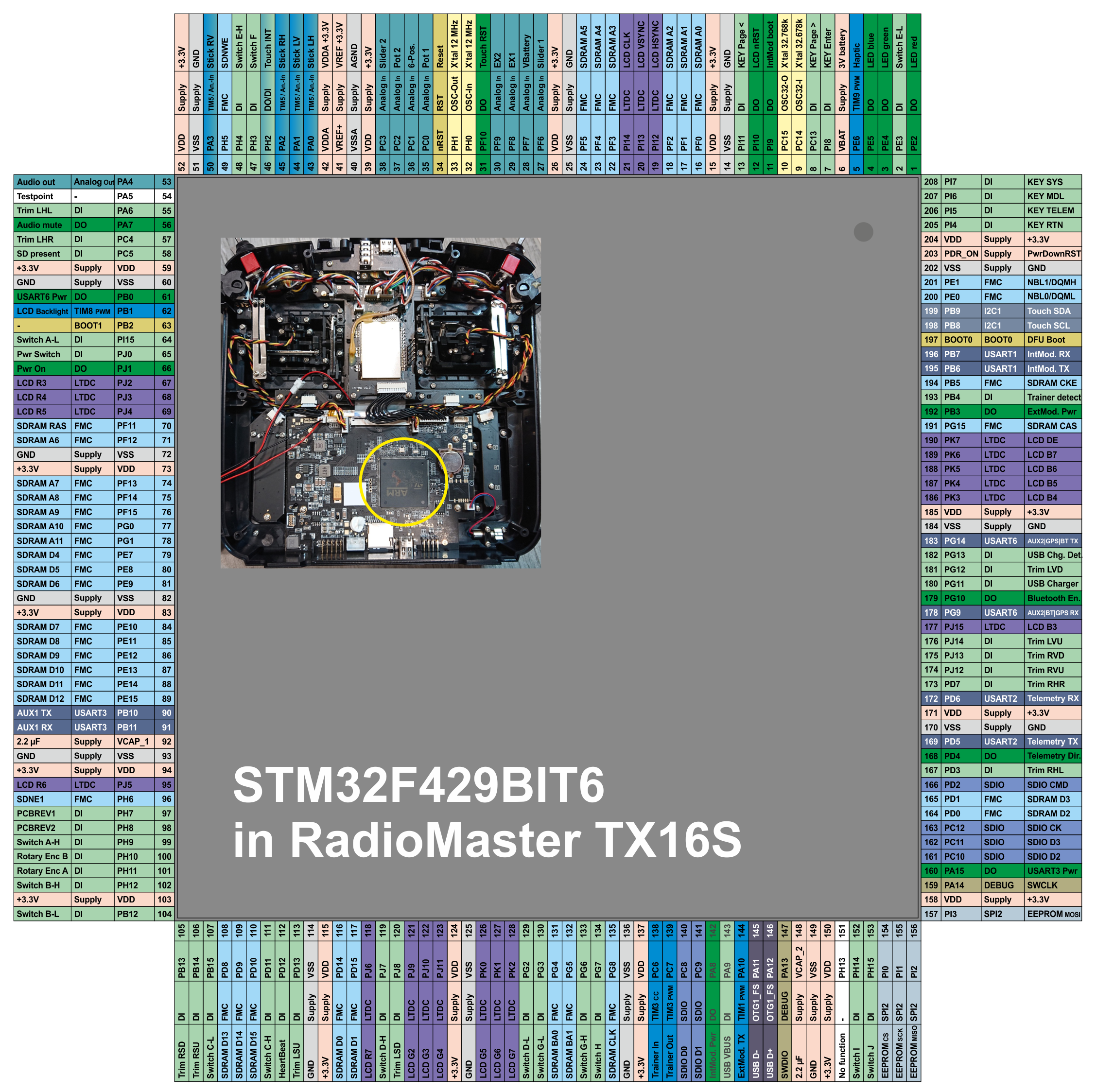
Why have I chosen UART8 for the GPS? As I have found, at least in case of my radio: USART1 is in use for the internal module; USART2 is for telemetry; USART3 is for serial port (debug) and for R9M ACCESS; UART4 needs the PA0 and PA1 pins as TX, RX terminals, but these are also used by the left stick; alternatively, PC10, PC11 can also be configured as TX, RX (not tried yet); UART5 needs PC12, PD2 but the parameter GPS_UART_GPIO can be set either to port C or D; USART6 is for Bluetooth; UART7 needs PF6, PF7, but these are not free. Alternatively, PE8, PE7 can be configured as TX, RX. - I have tried this last variant, but it fails. UART8 needs PE1, PE0 - this is what I am trying now, without success.

ViorelX commented 3 years ago

This is my compilation script:

@ECHO OFF REM Path where the firmware will be built SET BUILDPATH=D:\EdgeTX\Firmware

REM Path where the EdgeTX source can be found SET SRCPATH=D:\EdgeTX\Source

REM Path where the Qt compiler tools can be found SET QTPATH=C:\Qt\5.15.2

REM Firmware build options SET CMAKEOPTIONS=-DDISABLE_COMPANION=YES -DPCB=X10 -DPCBREV=T18 -DINTERNAL_MODULE_MULTI=YES

REM Include GNU ARM Toolchain in the path SET PATH=%PATH%;C:\Program Files (x86)\GNU Arm Embedded Toolchain\10 2020-q4-major\bin SET C_INCLUDE_PATH=C:\Program Files (x86)\GNU Arm Embedded Toolchain\10 2020-q4-major\arm-none-eabi\include SET CPLUS_INCLUDE_PATH=C:\Program Files (x86)\GNU Arm Embedded Toolchain\10 2020-q4-major\arm-none-eabi\include\c++\10.2.1;C:\Program Files (x86)\GNU Arm Embedded Toolchain\10 2020-q4-major\arm-none-eabi\include\c++\10.2.1\arm-none-eabi

REM Configure the build cmake -G "MinGW Makefiles" -S %SRCPATH% -B %BUILDPATH% -DCMAKE_PREFIX_PATH=%QTPATH%\msvc2019 %CMAKEOPTIONS%

REM Build the firmware, using the maximum number of cores mingw32-make -C %BUILDPATH% -j %NUMBER_OF_PROCESSORS% firmware

pause

ViorelX commented 3 years ago

I have found the SDRAM driver uses a lot of CPU pins, as commented in this source file, between the lines 72-92: https://github.com/EdgeTX/edgetx/blob/590ec5a9ed79bf1ed8fc8cb99601e37c7da0b0ae/radio/src/targets/horus/sdram_driver.c These include PE0, PE1 needed by UART8 and PE7, PE8 needed by UART7.

Therefore, I reconsidere UART4 with the alternative use of PC10, PC11. No other use have I noticed so far. This is the last chance.

This morning I have updated that lines for setting up the GPS, compiled the project, flashed to the radio and ... IT WORKS! A GPS icon appears on the toolbar.

Wait a little to change the wires of the GPS and I will announce if it really works.

ViorelX commented 3 years ago

I have soldered the TX, RX pins of the GPS (Beitian BN-800) to the 161, 162 CPU pins (to use the UART4 terminals PC.10, PC.11). It doesn't work. At startup I get the message 'Bad radio data' and the SD card is no more accessible. Otherwise, the radio works normally. On the 'statistics' page it appears the GPS, but it gets not fixed, even after a long run time.

I desoldered the RX, TX wires from the GPS and the SD-card works again.

pfeerick commented 3 years ago

Hm... that sounds strongly like PC10 and /or PC11 are being used by the SD card... Do any of those pins have SPI as a secondary function... perhaps chip select?

ViorelX commented 3 years ago

Yes, PC.10 and PC.11 are used by the SD card: https://github.com/EdgeTX/edgetx/blob/590ec5a9ed79bf1ed8fc8cb99601e37c7da0b0ae/radio/src/targets/common/arm/stm32/sdio_sd.c

And yes, both of them have an alternate SPI3 function.

ViorelX commented 3 years ago

UART5 is the only one port I have not tried yet. It uses PD2, PC12 (without alternatives), but these are used by the SD card too. Therefore, no more chance!!!

rotorman commented 3 years ago

@ViorelX huh, I am a bit amazed that you are wildly hooking up your GPS to pins who's usage you are not clear of. I would suggest first to map all the used pins of T18/TX18S. This could be done purely from EdgeTX source, as I have done for TX16S, by going through all the GPIO definitions in code:

After this knowledge, you can start making better decisions where you can add additional components and where not.

A bit radical, but even better solution would be to fully trace all the tracks on the PCB, as e.g. done here by removing the solder mask and delaminating the layers: https://www.rcgroups.com/forums/showthread.php?3868769-Blog-16-RadioMaster-TX16S-mainboard The latter method sacrifices minimally one board though.

pfeerick commented 3 years ago

Ouch... well, that explains the SD card error! 😢 It sounds like you may not be able to have GPS unless something else like the bluetooth gets the boot!

brainbubblersbest commented 3 years ago

I think thats the reason for the additional spi connected 12channel adc7952 IC @rotorman mentioned on that Radio. And why there is a free UART 4 for exclusive the GPS. Because less connected adc Lines on stm. A Solution here could be changing the UART usage at runtime like he said someday in the future. 🙂

There is also a Gyroscope/Accelerometer Board on the x12s that never had worked with Opentx and is complete useless. I Think it's connected to another uart/spi thats only available on that Radio.

Exit: yes this is confusing, sorry. It's Adressef to the fact He tried the Layouting/pin functions from the x12 on that Radio. But there is in fact not a Single free one.

rotorman commented 3 years ago

@brainbubblersbest I believe you are confusing radios - I said X12S has Texas Instruments ADS7952. Although I have not yet seen T18/TX18S myself, looking at the images found on the net, I do not believe they come with external ADC and use the STM32F4 internal ADCs instead (like most OpenTX/EdgeTX radios).

brainbubblersbest commented 3 years ago

Thats what i mean to say. He will connect gps+Bluetooth+eaMOD the same time. But All x10 based Radio processor Pins are already in Use. So the UART4 Pins are here used with alternate Function. (left gimbal?)

Only way to use more then two Devices would be with a connector and plug in the stuff he need for his used setup and Model. Then configure it in the Hardware Page. Like you add a BTModule to inav. But in exchange remove the Lidar.

rotorman commented 3 years ago

SPI Flash is currently unused on OpenTX/EdgeTX on color radios, so that would be one option to go (e.g. with SPI to UART converter IC there).

brainbubblersbest commented 3 years ago

I read about other Plans with the spi Flash for edgetx. For that Single Radio this would be a solution. 🙃

rotorman commented 3 years ago

Even with future usage of SPI, you only need a single dedicated ChipSelect line (any GPIO) for the UART converter, which would make it possibly still a viable option if no hw-UART/USART is available.

ViorelX commented 3 years ago

@ViorelX huh, I am a bit amazed that you are wildly hooking up your GPS to pins who's usage you are not clear of.

@rotorman, that's because I am a simple hobbyst, not so much experienced. I am new to OpenTX, github and such radios. I purchased a Radioking a few months ago, but due to lack of time, I didn't use it yet. But I strongly want to modify it. I am also amazed to see your great work. I have studied your blog and now I am much better documented than yesterday. Thank you very much for all that stuff. Now I know my radio has at least these unused pins: PA5, PA13, PA14, PA15, PH13.

Here is my last solution: The left stick (gimbal) uses PA0, PA1. I'll cut the gimbal wires connected to PA0, PA1 and move them to PA13, PA14, which belong to the (unused) Serial-Wire-Debug (SWD). Instead, I will connect the GPS TX, RX wires to PA0, PA1, which can be configured as TX, RX pins of UART4. Is this a bad solution?

pfeerick commented 3 years ago

@ViorelX I think part of the amazement is due to the fact that you could let the magic smoke out of the radio by doing things that way... 😮 As long as you are aware of this risk... 😉

brainbubblersbest commented 3 years ago

@ViorelX huh, I am a bit amazed that you are wildly hooking up your GPS to pins who's usage you are not clear of.

@rotorman, that's because I am a simple hobbyst, not so much experienced. I am new to OpenTX, github and such radios. I have purchased a Radioking a few months ago, but due to lack of time, I didn't use it yet. But I strongly want to modify it. I am also amazed to see your great work. I have studied your blog and now I am much better documented than yesterday. Thank you very much for all that stuff. Now I know my radio has at least these unused pins: PA5, PA13, PA14, PA15, PH13.

Here is my last solution: The left stick (gimbal) uses PA0, PA1. I'll cut the gimbal wires connected to PA0, PA1 and move them to PA13, PA14, which belong to the (unused) Serial-Wire-Debug (SWD). Instead, I will connect the GPS TX, RX wires to PA0, PA1, which can be configured as TX, RX pins of UART4. Is this a bad solution?

I really like this "lets Do it" mindset 😆 I would try it. Knowing something Bad can happen🤣 But no risk no fun 🥳

rotorman commented 3 years ago

@ViorelX SWD is an awesome programming & in-circuit-debug channel to the µC/radio to see what is happening during execution. Personally, I would not sacrifice SWD and instead find other pins to be re-mapped. For more about in-circuit debugging plz see: https://github.com/EdgeTX/edgetx/wiki/In-Circuit-Debugging-with-Qt-Creator As a modder, I think this tool will come very useful to you.

If you need further free pins, consider again SPI. Similarly as done in X12S, you could add a small custom ADS7952 PCB to sample up to 12 of your analog inputs, e.g. all your sticks, sliders and pots, freeing up many pins. If done right, the analog to digital conversion quality can be higher than the current solution with STM32F4 integrated ADC module. And the best part, the code to read out ADS7952 is already available in https://github.com/EdgeTX/edgetx/blob/2.4/radio/src/targets/horus/x12s_adc_driver.cpp , making integration easy.

ViorelX commented 3 years ago

I give up the GPS momentarily. There is no simple solution. My last idea to use the SWD pins as input pins for the left gimbal doesn't work: that pins cannot be configured as ADC inputs. Only certain pins may serve as inputs for the 3 ADCs with 16 channels and no more appropriated pins are available. Therefore, the SWD will be preserved as it is. Eventually, could the SWD work with a GPS with I2C interface? The use of an ADS7952, as done in X12S, would be a great solution, but at the moment, it is too complicated for me. It requires a lot of work and time. Now I am looking to put a GPS with SPI interface on SPI2 (the unused SPI of the EPROM, i.e. PI0, PI1, PI2, PI3 pins). I need a GPS like this: http://www.farnell.com/datasheets/1821035.pdf

rotorman commented 3 years ago

Eventually, could the SWD work with a GPS with I2C interface?

No, SWD is only for debugging, you cannot control it from firmware.

sprrrry commented 3 years ago

I don't know much about all this but with the help of @rotorman's tx16s pcb diagram, I found one of the external uart of tx16s is connected to the bluetooth module pads in the pcb and the other is connected to the debug uart. Both of these uarts are broken out in the t18 pcb, so can't a gps be installed by connecting to the same uart as in tx16s and make similar code modifications? Please correct me if I'm wrong...

ViorelX commented 3 years ago

No, because I have put a bluetooth module there (UART6). And at the debug port (UART3) I have made connections for R9M ACCESS.

brainbubblersbest commented 3 years ago

If you dont have Touch, you can use 198 and 199 i2c1. Its used for gyroscope on the x12s. Bu not implemented with opentx or edgetx And not used on x10 Radios without touch

brainbubblersbest commented 3 years ago

InterfaceDocumentation X12S

ViorelX commented 3 years ago

Thank you, but I have touchscreen.

Is this a good tool for SWD? https://ardushop.ro/en/home/1288-programator-compatibil-st-link-v2-stm8-stm32.html It's the cheapest I can get.

rotorman commented 3 years ago

Have a look at Segger J-Link EDU Mini, the cheapest original for non-commercial purposes: https://www.segger.com/products/debug-probes/j-link/models/j-link-edu-mini/

K2AAE commented 2 years ago

InterfaceDocumentation X12S

Now do this to the T18 Pro V2 mother board! I like the lighted switch labels of the T18 but not having access to uart for GPS or other functions means this unit will be replaced.

rotorman commented 2 years ago

@K2AAE The easiest to get internal GPS on T18 IMO, would be to attach it to Bluetooth module pads:

grafik

I would look for alternative hookup options, only if you are planning to use FrSky Bluetooth module.

ViorelX commented 2 years ago

OK, but I already have mounted the FrSky Bluetooth module on its pads. Actually, it doesn't work for me: on my phone it appears in the list of devices which can be connected by Bluetooth, but I didn't managed to pair it. I also tried to connect T18 with Inav Mission Planner, without success. The only way to connect it is via USB.

rotorman commented 2 years ago

I have used FrSky BT module in RM TX16S successfully with the HeadTracker Pj. https://github.com/dlktdr/HeadTracker and https://headtracker.gitbook.io/head-tracker/ (basically Arduino Nano 33 BLE). It also pairs OK with another FrSky BT module. Some info about the protocol used by the module: https://www.rcgroups.com/forums/showthread.php?3493859-RadioMaster-TX16S-16Ch-2-4ghz-Multi-Protocol-OpenTX-Radio-System/page662#post46878713

sdellava commented 1 year ago

have mounted the FrSky Bluetooth module on its pads.

Hi, I'm trying to install a GPS on a Jumper T18 Pro. Did you get it works?

sdellava commented 1 year ago

@K2AAE The easiest to get internal GPS on T18 IMO, would be to attach it to Bluetooth module pads:

grafik

I would look for alternative hookup options, only if you are planning to use FrSky Bluetooth module.

I've followed your suggestion, but nothing happen. GPS is 9600 bps and I've configured it on the AUX2. but nothing happen on the radio:

image image

sdellava commented 1 year ago

Solved. It turned out the the Bluetooth pad pinout reported in the images above is wrong. This is the correct pinout:

image

The highligthed pin have to be connected to the GPS TX pin.