Edzelf / ESP32-Radio

Internet radio based on ESP32, VS1053 and a TFT screen.
GNU General Public License v3.0
964 stars 227 forks source link

Audio Transformer #513

Open Beppi4U opened 1 year ago

Beppi4U commented 1 year ago

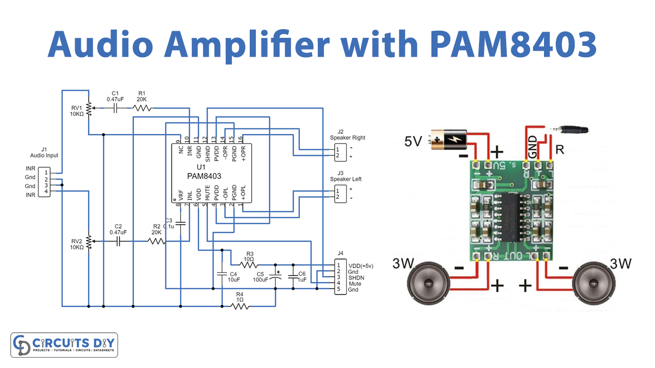
Hi! Are these little audio transformers, on the PCB, connected between Mp3Module and amp or between amp and speaker(so i guessed)?! Happy new year and thanks!

Rainer-G commented 1 year ago
Hi Andy, look at the schematic attached, the transformers are between the MP3 Module ( VS_out in the schematic ) and the amplifieer ( PAM in the schematic ). VREF and Pin 2 of the PAM ( solid lines ) must not be connected! You don’t need the resistors, I used them to reduce the level by 50 %, my PAM was too sensitive! Happy New Year and good luck Rainer Von: AndiLübeckGesendet: Samstag, 7. Januar 2023 17:40An: Edzelf/ESP32-RadioCc: SubscribedBetreff: [Edzelf/ESP32-Radio] Audio Transformer (Issue #513) Hi! Are these little audio transformers connected between Mp3Module and amp or between amp and speaker(so i guessed)?!Happy new year and thanks for help!—Reply to this email directly, view it on GitHub, or unsubscribe.You are receiving this because you are subscribed to this thread.Message ID: ***@***.***> 
petervflocke commented 1 year ago

Hi Andy, look at the schematic attached, the transformers are between the MP3 Module ( VS_out in the schematic ) and the amplifieer ( PAM in the schematic ). VREF and Pin 2 of the PAM ( solid lines ) must not be connected!

Hello @Rainer-G, where I can find the schematic? There is just a simple list of connections in the ESP32-radio.pdf file. Saying MP3 Module have you meant vs1053? I cannot find there VS_out pin. On the PAM 8403 (link) you mean pin 8 VRF and pin2 PGND? Is it necessary to break the existing connection?

Your assistance is very much appreciated. Cheers Peter

Rainer-G commented 1 year ago
Hi Piotr, the MP3 Module is the VS1053, I attached this extract of my Board layout for Andy:  The VS_Out Pins war named so on my circuit diagram, the VS1053 has a 3,5 mm jack without names, so if you plug in a cable, the ground wire is the Vref and the other two are analog right resp. Left. My PAM8610 also has a similar jack: So, if you have the same configuration and do not want to de-solder the jacks, simply cut a standard 3,5 to 3,5 mm audio cable in the middle and connect the open ends with the transformers as above. Good luckRainer Von: petervflockeGesendet: Donnerstag, 12. Januar 2023 11:48An: Edzelf/ESP32-RadioCc: Rainer-G; MentionBetreff: Re: [Edzelf/ESP32-Radio] Audio Transformer (Issue #513) Hi Andy, look at the schematic attached, the transformers are between the MP3 Module ( VS_out in the schematic ) and the amplifieer ( PAM in the schematic ). VREF and Pin 2 of the PAM ( solid lines ) must not be connected!Hello @Rainer-G, where I can find the schematic? There is just a simple list of connections in the ESP32-radio.pdf file.Saying MP3 Module have you meant vs1053? I cannot find there VS_out pin. On the PAM 8403 (link) you mean pin 8 VRF and pin2 PGND? Is it necessary to break the existing connection?Your assistance is very much appreciated.CheersPiotr—Reply to this email directly, view it on GitHub, or unsubscribe.You are receiving this because you were mentioned.Message ID: ***@***.***> 
petervflocke commented 1 year ago

Hi Rainer, thanks for your quick response. I see you use the PAM8610 not the simple one PAM8403, that clarifies my doubt. You just separated with the transformer audio-out at MP3 with audio-in at the amplifier side, no additional filters or whatsoever.

As you answered via an email, I believe, github removes all attachments, that the reason we do not see any attachments.

Thanks and best regards P.

Beppi4U commented 1 year ago

Hallo! Sorry für die späte Rückmeldung! Ich versuchs mal auf Deutsch auch wenn das etwas gegen die Regeln ist! Ich habe an meinem mp3 modul den 3.5mm Ausgang auf der Rückseite der Platine mit kabeln angezapft! Da hab ich Gnd , linker und rechter Kanal. Meine Frage wäre wie ich die jetzt mit den Transformern verschalten muss?? Der Amp bekomt seine Spannung nicht vom esp32 hängt aber an der gleichen Quelle! Eventuell kommen die BrummStörungen schon vom Netzteil rüber.... Gruß Andi

Edzelf commented 1 year ago

Als je een gescheiden voeding hebt voor de versterker, dan moet de GND van de versterker niet verbinden met de GND van de ESP32, maar met de common van de 3.5 aansluiting. Geen trafo's nodig dus.

petervflocke commented 1 year ago

Der Amp bekomt seine Spannung nicht vom esp32 hängt aber an der gleichen Quelle! Eventuell kommen die BrummStörungen schon vom Netzteil rüber....

Hi Andi, If you have a common ground (GND) for MP3 and amplifier it does not make IMHO any sense to use transformers. You use them to isolate the grounds. See the documentation capitel "Amplifier and power circuit." there you have two power sources with a separated gnd during operations. The potential distortions may come not only from power supply but also from ESP and mp3.

dheydeck commented 1 year ago

Just for the sake of clarity regarding grounding the output from the VS1053- see https://learn.sparkfun.com/tutorials/mp3-player-shield-hookup-guide-v15: To quote:

the signals coming from the VS1053 are DC coupled. This means that the alternating-current (AC) audio signals are riding on top of a 1.25 V DC offset.

In spite of the "G" in it's name, GBUF is not ground - in the pin descriptions, the datasheet specifically warns us "Common buffer for headphones, do NOT connect to ground!"

This may not be relevant in this particular case, but may be of value for anyone searching on whether the VS1053 output can be grounded. Rather, isolating transformers or capacitors should be used. I have a VS1053 board of the type commonly available from Internet vendors and have measured the voltage- 1.25V- between the DGND input pin and output jack sleeve, which might be expected to be grounded. The current VS1035 board made by Adafruit has isolating capacitors installed.

Beppi4U commented 1 year ago

Got the Audio Transformers in the Mail....so quick soldering a little board aaaaand! The result is much better than before! Have to reasemble my toaster radio and close holes! Will present a video when its done! Thanks everybody for helping me! Andi

20230117_181932.jpg

20230117_181922.jpg

20230117_181908.jpg

garbo5005 commented 1 year ago

I apologize this is off topic but what is the graphics on the display, looks like a equalizer graph?

Beppi4U commented 1 year ago

Just go for searching ' lotfi spectrum analyzer ' or ' lotfi esp32 radio equalizer ' ....just a few lines of code to add on the original sketch! Greetings Andi

petervflocke commented 1 year ago

@garbo5005: https://github.com/blotfi/ESP32-Radio-with-Spectrum-analyzer