Emile666 / stc1000_stm8

STC1000p for the STM8 microcontroller (HW version WR-032)
GNU General Public License v3.0
45 stars 10 forks source link

Temperature sensors not showing real values #14

Open ffpp2003 opened 1 year ago

ffpp2003 commented 1 year ago

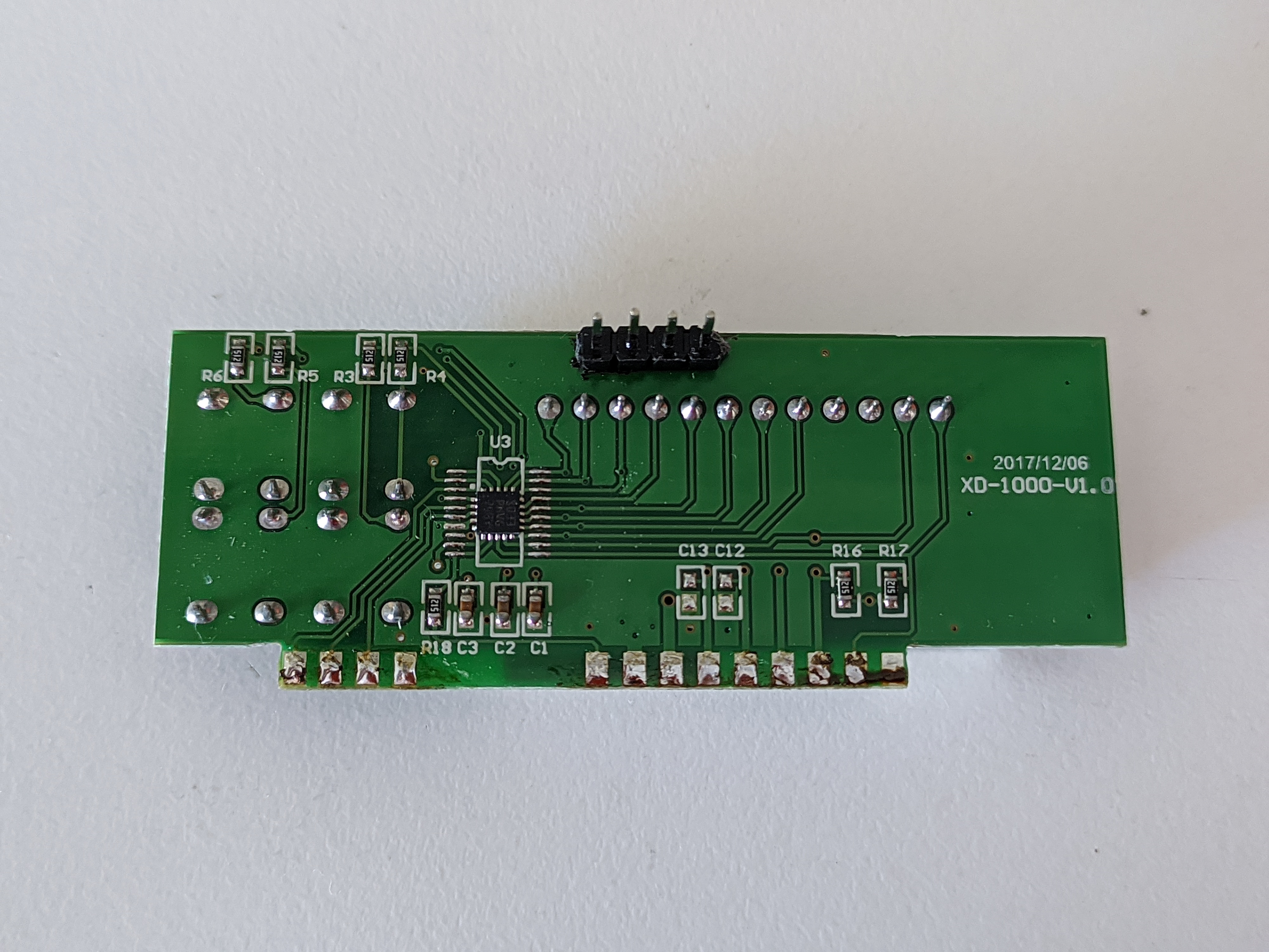
I've got this STC-1000 that has the same box as emile (like the WR-032-v1), but has a different PCB name. This one is the XD-1000-v1.0. The backplane looks to be pretty similar to the WR-032 v2 board . The only difference that i was able to find is that this version (compared to the WR-032-v1) uses the UFQFPN20 package of the STM8S003F3, while also having the pads and silkscreen for the TSSOP20 version of the same chip. I'll add some photos of the front-pcb and the power pcb. The problem i'm experimenting is that temperatures do not get read properly, in the sense that both numbers (NTC1 and NTC2) start at 25cº, but the NTC1 starts to raise up and the NTC2 starts to go down, until they stabilize at 40cº and 1cº respectively. I only plan to use this STC with one temperature probe, and no SSR or any extra mod. I've tried using IAR to reduce or even disable the number of averaged measurments, but it seems to have no change at all. What else can i try to fix this problem?? IMG_20221007_153840 IMG_20221007_153819 IMG_20221007_153831 IMG_20221007_153853

Emile666 commented 1 year ago

I checked the datasheets of both packages and they look the same. Interesting way of combining these 2 packages, I have not seen it before. The NTC1 and NTC2 readings go to pin 20 (NTC1, AIN4/PD3) and pin 19 (NTC2, AIN3/PD2). This is the same as on the QFPN package. Can you check if the voltages show up at pin 19 and pin 20 when you connect the sensor inputs to GND and VCC? That should be 0V and 3.3V respectively (leave the sensors off). Since these temperaturesensors are multiplexed with the A and B leds of the display, can you check if the display is really Common-Cathode (CC)? If it is common-anode, this could be the cause of the problem.

ffpp2003 commented 1 year ago

So, i did what you told me to do. When floating (nothing connected on the screw terminal) i get from 3.3v to 4.5v. Thats what i was able to measure with my multimeter. I could get to have an oscilloscope, but it will be in some days, when i go back to work. When the screw terminal is connected to GND, the shown temperature starts to go down in a slow manner, like 1 to 1.5c per second. Measuring pin 20 (not actually pin 20, but the 1K resistor that is on the big PCB, touching of course the side that connects directly to the pin20) i get from 1.1v to 2.3v. Connecting the screw terminal to 5V i get voltages from 3.3v to 4.5 and ocassionaly dipping to 2.3v. I did all tests using the mains power supply and also using the STLINK voltage lines, to have a clean power source and a noisy one. Both tests gave similar results Checking the 7segment display, its the same as in the schematic. Pins 1 and 2 are connected to vcc through 5.1K resistors and pins 3 and 4 are connected to pins 1 and 2 of the tssop pads, and connected to the respective pins on the qfpn pads. This test i think was unecessary because if it was the wrong common, all segments would be inverted, which is not the case. So, no hardware issues from what i can see. What could it be??

Emile666 commented 1 year ago

What I can see from your picture is that R23 and R24 are not populated, so the NTC2 value is not connected to the microcontroller. That explains why your NTC2 reading is not working. If you want to have proper NTC2 values, you need to solder these two resistors back in place. R23 should be 10 kOhm (103) and R24 should be 1 kOhm (102).

W.r.t. the NTC1 reading, it could be that the C8 capacitor (between R21 and R22) is the problem. Simply remove this capacitor and the NTC1 reading will probably be oke.

Can you try this and let me know if that works?

ffpp2003 commented 1 year ago

Yes! Removing C8 did the trick! now it works perfectly fine. I tested it with my hot air gun and with an ice cube and it works perfectly fine. I would've never figured it out by myself. The weird thing is that the capacitor seems to be allright. I measured its capacitance with my multimeter and it gives 106nF, which is between the 5% tolerance. So, thats weird.

Also, now that you've talked about NTC2, i want to ask you, is there a way to "completely remove" NTC2 from the firmware? Like, in the orignal STC1000+, there is a "flavor" which only has NTC1. Peeking around the source code, i wasnt able to find a macro or a define that specifically says "NTC2", where setting it to false disables and removes everything related to NTC2 from the firmware. I guess if there isnt something like that, the only way would be to manually remove all those parts from the code, but i was just wondering if there is that firmware "flavor" thing on your port.

Anyway, thanks for helping and sharing this awesome mod!

Emile666 commented 1 year ago

There is no such thing as a macro for that. Instead the parameter Pb2 is used for this. If you set this value to 0, the 2nd temperature probe is not used in the firmware. So you can enable/disable this run-time with the keys on the front. The original firmware needed to do this because of very limited available memory. The STM8 has a bit more memory, so I choose to add this as a parameter instead of a macro.

I would suggest to leave it to 1 and populate the missing resistors, since the firmware then uses the outside temperature to determine whether or not to enable heating/cooling. If outside temperature is warm enough, heating is not enabled. Same for cooling: if outside temperature is cool enough, cooling is not enabled. This prevents heating/cooling cycles and saves you energy.