FilipDominec / rp2daq

Raspberry Pi Pico firmware for universal hardware control & measurement, along with a user-friendly Python frontend
MIT License
27 stars 4 forks source link

RPI Pico Carrier Board #13

Closed epsi1on closed 5 months ago

epsi1on commented 5 months ago

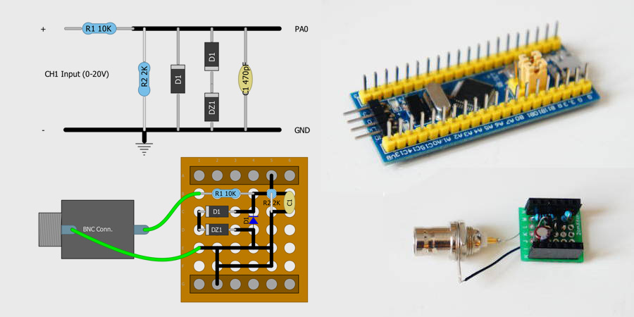
Hi, Thanks for great project. could you suggest a simple carrier board for RPI pico to turn it into oscilloscope? A very simple one like THIS (with 2 resistor, 3 diode and 1 capacitor) could work with PICO version? I am also wrapping up to make next version of C# oscilloscope.

FilipDominec commented 5 months ago

Sure, the analog input part (https://chiptron.cz/images/news/HS101/hs101_schematics.jpg) will protect your RP2 from being zapped by overvoltage, and will divide input by 6 (so full range of the ADC is again about 20 V). I don't know if this is the carrier board what you mean.

If it were up to me, I would probably add a reasonably fast opamp to the input with say 10× amplification, positive/negative zero level shift, and also the input voltage divider should have a switch that would change voltage ranges like 0.5, 1V, 2V, ... 20V, 50V.

Just like on a real oscilloscope.

epsi1on commented 5 months ago

i think by voltage divider with switch, you mean something like this image I was thinking as transistor is kind of switch, do you think that this divider could digitally be controlled with PWM pins and set of transistors instead of manual switches? The PWM pins of Pico are free and i think i can use them for this purpose. edit: turned out it can (found from here)

FilipDominec commented 5 months ago

Proper analogue design of an oscilloscope is somewhat out of scope of this project. (No pun intended.)

In short, you will want the divider to protect the pre-amp, so it should be the first part after the input plug.

Also if you expect the voltage division to go roughly like 1/10, 1/5, 1/2, 1/1 ... you need to change the resistor values. My suggested ordering of resistors would then be 1M on input and then something like

R_total = np.array([ 1/(n-1+1e-9) for n in [50,20,10,5,2,1] ] )                                                                                                     
R_partial = R_partial = np.hstack([R_total[:1], R_total[1:]-R_total[:1] ] )

resulting in megaohms of the consecutive resistors:

array([2.04081633e-02, 3.22234157e-02, 9.07029478e-02, 2.29591837e-01, 9.79591836e-01, 1.00000000e+09])

You can get along without SW1 if you don't use zero calibration often.

FilipDominec commented 5 months ago

If you are OK with this, let's close the topic.

When I make some reference design for a future rp2daq-oscilloscope, I will post it in a separate project.

Further electrical engineering may be better discussed by e-mail, or even better, on https://electronics.stackexchange.com/

epsi1on commented 4 weeks ago

just for information, i did some dummy design for an elementary oscilloscope hardware for RPI pico without any active component! (used components are limited to resistor, capacitor, diode, switch and BNC connector. (link) I'm very happy with it, works very well with a good USB cable. Thanks for sharing this project.

FilipDominec commented 4 weeks ago

Good. I am still having the 100Msps oscilloscope/log-analyzer in mind, though there are much more scientific tasks to be done before.

epsi1on commented 4 weeks ago

Good. I am still having the 100Msps oscilloscope/log-analyzer in mind, though there are much more scientific tasks to be done before.

That one would be great. I think the wpf UI have reasonable performance. it gets continues 500k samples without any missing data. The scope did even visualized a 120 Mhz sin wave (produced by a SI5351 module) on the monitor like a normal sin wave! (when i directly connected the signal to ADC pin without any resistor in between). but due to Nyquist theorem it didn't detect the right frequency but the sin wave shape was almost perfectly detected... I'll wait for the 100M scope, if it is USB based then I think can do some help...