 FormerLurker
commented
3 years ago
FormerLurker
commented
3 years ago @mrx23dot, ulendo looks like it is firmware, is it not? Not sure what's going on there, but it looks like maybe their motion planner is not only based on segments, like marlin. I've actually been thinking about this as well, and it makes sense. Curves are predictable all along the path of the curve, but you never know where the next G1 is going to take you :)
Regarding G5, I've thought about it. The process is a bit more complicated and the math isn't quite as pretty. I'm sure you could achieve better compression and tool-paths with G5. Without implementing it, it's hard to tell how much exactly. I don't think I've ever seen any complicated gcode with G5s before for reference.
I think another barrier (not one that is impossible to overcome) would be firmware. SO SO many people think arc welder is broken because their firmware is old, has arcs disabled, or has serious flaws in the implementation. That would change with time, of course. Anyway, it is still a good idea, and one I've put a lot of thought into, and I'll keep it on the agenda for further study.
 mrx23dot
 5axes
5axes there are some spline movements, only not at the correct place.

 DeepSOIC
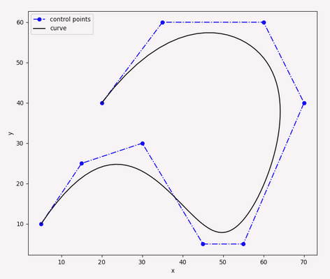 Looks promising.


 xorza
xorza wookie76
 tasmaine
 Flyordye
It might worth adding a branch for G5 interpolation for playing around.
This study compares G1 (linear) / G2_3 (arc) / G5 (cubic spline) movements and concludes: https://www.sciencedirect.com/science/article/pii/S2351978919311059
The authors already started monetizing on it: https://www.ulendo.io/ https://www.kickstarter.com/projects/s2a/ulendo-better-faster-3d-printing