 macdroid53
commented
1 year ago
macdroid53
commented
1 year ago I see that most issues have tags, but i missed how to set the tags before creating the issue. Now I can't figure out how to add them after the fact.
Closed macdroid53 closed 8 months ago
macdroid53
commented
1 year ago I see that most issues have tags, but i missed how to set the tags before creating the issue. Now I can't figure out how to add them after the fact.
 howie-j
commented
1 year ago
howie-j
commented
1 year ago The maintainers can add tags, add issues to projects etc. @luzpaz perhaps add this issue to the assembly project?
@macdroid53 what solids can the part workbench create, is there a list (or could you make one)?
 luzpaz
commented
12 months ago
luzpaz
commented
12 months ago @PaddleStroke just a heads-up
 PaddleStroke
commented
12 months ago
PaddleStroke
commented
12 months ago Yes for now only part design bodies and App::Parts could be added. But there's no strong reason for this limitation so we can also accept Part wb objects directly.
 mno13
commented
11 months ago
mno13
commented
11 months ago Shouldn't it be other way around? Assembly should accept only Parts (App:Part), but inside part there could be anything? Part design bodies; Part solids, surfaces; some imported mesh from 3d scaned object; even single Draft wire as placeholder (example - some linking rod in mechanism) etc.
Ability to asemble anything with anything (Bodies with Parts and so on) leads to chaos and creating BOM seems imposible. BOM shouldn't be simple list of assembled... "things" but there are also important properties to be extracted. In that case there should be single type of object to be assembled, so every asembled object has the same properties.
macdroid53
commented
11 months ago @mno13 I disagree. I shouldn't need a Part (Std_Part) to add nuts, bolts, etc. to an assembly. What you describe, I think is more of a sub-assembly. A solid created in the Part workbench is a valid line item in a BOM. A nut created with Fasteners workbench is a line item (there may be ten of the same nut and that should end up as a count on the line item). A gear made with the Gear workbench is also a valid line item. etc. Properties to be extracted are a property of the object, so there shouldn't be any confusion.
mno13
commented
11 months ago Fasteners are IMO great example of using Part properties. In this case, there should be standard property called something like "source" with value like "Purchased" or "Standard" ("Standard" as in "according to ISO/DIN... Standard").
Ultimately, there should be option for predefined property values using templates. In this example - "source" could be "Purchased" or "Manufactured" , or for other user "Purchased COTS", "Standard", "Machined", '3D Printed" etc. Depends on user workflow, but basically its range is constant for given workflow.
Moving to production documentation logic and keeping things simple:
I don't fully get your idea about sub-assembly. Could you explain what you have on your mind?
macdroid53
commented
11 months ago The original intent of the the Part (Std_Part) container is just that a container. It is a container that happens to have an Origin object and anything put in it references that Origin object. And, it can contain a Part WB solid, a PD Body, etc. If the Part (Std_Part) is moved it's contents move with reference to the Origin object. The Part (Std_Part) has been a pseudo viewed as a sub-assembly or even top assembly since it was introduced.
mno13
commented
11 months ago Part it's a perfect container that can contain anything. But on "real" assembly level IMO we should assemble more "physical" things. And from end user point of view that sould be as simple as "we can assemble only parts (and other assemblies), everything that is going to be assembled (and is not an assembly itself) should go inside part".
There is an instance where line between part and sub-assembly is blurred - inseparable assembly.
One sidenote about fasteners etc. On one hand that would mean a need to modify current workbench to add fasteners inside new Part. But on other hand, the long term solution should be more universal, and standard part catalog shoud have ability to store any custom parametric part.
macdroid53
commented
11 months ago I disagree. There is no particular need for a container. IMO, it is just adding a wrapper to something that can stand alone. Especially for fasteners. Also, if it is indeed a wrapper for a sub-assembly, then it should definitely NOT be called a Part. There is far too much confusion in FC about the term "part" already.
mno13
commented
11 months ago I forgot about "Part" naming confusion in FC. Using name "Part" for this container is unfortunate in this context, using something other, for example: "component" would maybe be more appropriate.
But my main remark still stands. There should be universal wrapper so Assembly structure is straightforward. Even more - there IS a universal wrapper (std:part) so why we won't use it?
Situation, where user can assemble anything with anything is unmanagable in long term (maybe with good PDM, but PDM can be pain itself). I'm thinking about large projects with multiple designers.
It's an industry standard. Assembling only subassemblies and parts. Why reinventing wheel?
Assembly shouldn't be only about "putting things together". It's also about manageability of design.
Side note: in Catia, there is only posiblity to assemble (sub)assemblies, because part is a special case of assembly file cointaing single part. I din't wanted to bring any specific CAD as example before, but it's one of few examples where things are done a bit diferently than in mainstream CAD aplications, at least from user POV.
macdroid53
commented
11 months ago I just don't see the issue. I should be able to put 10 fasteners, 10 gears, etc. into an assembly without having to add each to a container. It can contain properties that define it's details like name, source, material, etc.
mno13
commented
11 months ago I agree that no extra work should need to be done when placing fasteners etc. See one of my previous answers - I think that ultimately the standard component library should be modified to work with std:part and generate elements that are themselves "parts".
Having a common parts container means that the available properties for BOM items are the same and adding custom properties is easier (it has to be done in single place). When it's possible to add everything to an assembly, managing standards and creating consistent BOMs based on them is a nightmare.
macdroid53
commented
11 months ago I just don't see the issue. A general purpose, extensible, BOM object is defined. Anything that gets added to an assembly gets a BOM object activated/added. The user needs to do nothing unless they want to add BOM details to the item being added to the assembly.
mno13
commented
11 months ago Why anyone would want to define additional "BOM object" ? And why create new object type when anything placed in assembly should be "BOM-able" by default? When "part" (Std:part) will have all the properties needed for BOM ?
On BOM activation topic - it should be a mere "Part" property - "exclude from BOM"
macdroid53
commented
11 months ago Add it to a Std_Part or add it to any other object. A developer creates it once. The data about the component has to be entered at some point. Why can't a Part workbench Extrusion have a BOM info object? That should be a mere property. Why must it have a Std_Part wrapper, to include BOM info? If the Std_Part has a BOM object, why can't anything else?
mno13
commented
11 months ago BOM info should be extracted directly from Part (stdpart) properties. That's all.
But is there even a real world use case for your example? Extrusion object as "item"? Extrusion is not an item, it's just a mere model feature (yes, i know - a part, not part_design feature, but still). It leads to bom like this:
No | Name | Material | [ ...] | Qty 1 | Welded bracket | S235JR | [ ...] | 2 2 | ISO 4762 - M6 x 20 | A2-70 | [ ...] | 10 3 | Hole 5 | ??? | [...] | 2
See a problem? Not everything is BOM-able and list of things that could be assembled should be restrited to some common object type.
What about imported STL for mockup? Proper way is to put this into container with "real" LCS and not to try use just Mesh object in assembly.
@PaddleStroke should this be discussed in larger group? Maybe on FC forum? I think question "what could be assembled" is quite important one.
macdroid53
commented
11 months ago I would agree that this should be discussed by a larger audience. What I hear you saying is if I make ten different components in Part Design, each with a single revolve feature, and add them to an assembly they each can have a BOM object. But, if I make the same 10 components, each with a single Part workbench revolve, they can't have a BOM object. But, a component made with Fastener or Gear workbench can have a BOM object. I'm not suggesting a hole, which is not a solid, be given a BOM object. And, no one would add a hole to an assembly. Look at the very last image in the example at the end of this link. The Body in the left image can be added to an assembly. If I've designed Cut001 on the right, why should I be precluded from having BOM information and use in an assembly? https://wiki.freecad.org/Part_and_PartDesign
mno13
commented
11 months ago Example with hole was exargated to the extreme, to show where it's going when we're able to assemble anything with anything.
I'm against assembling bodies. In given example neither element (Body vs Boolean result) should be element of assembly.
Catia structure example:
Solid Edge structure example:
Inventor, Solidworks etc works in similar manner. STEP file structure is similar.
There is always some common container where all the modelling takes place, and just after that these 'containers' are assembled (assembly features aside)
macdroid53
commented
11 months ago So, you don't want the integrated assembly bench to work as it apparently does?
Am I using it wrong?
mno13
commented
11 months ago Not really. Here is an example of assembly structure that is mostly on par with other systems:
Making this example I found out that there is currently no posibility to put assembly into assembly :/. Also instance naming is not great.
macdroid53
commented
10 months ago I still am not convinced that a Body object can carry BOM info and other objects can't.
I'll buy, that it can be arbitrarily decided that to be in an assembly an object must be in a container. But adding a container is tad amount to adding a BOM property to a given object.
PaddleStroke
commented
10 months ago As there are no technical limitations to prevent the user to use solids directly I am not enthust to add a limitation to force the user to use Parts containers. I understand both positions, but one is asking to limit capabilities that are not hurting. Say if you want to include all your solids in parts you can. I guess it is possible to add a preference like 'Allow only Parts in assembly' that would prevent user from using solids directly. Or alternatively that would create Parts containers automatically when the user insert solids.
Nested assemblies need a bit more work.
mno13
commented
10 months ago @PaddleStroke
At least preference for allowing only parts in assembly would be nice to have. Work on larger projects with multiple designers require a way to enforce way of building assembly on whole team.
Automatic creation of Part container during solid creation is de-facto a standard way of working for most of the CAD systems on the market. Part containers are separate files, but still - each assembled component is inside some kind of container (mostly shown to user as separate file).
@macdroid53
Adding BOM property vs "Universal Part container" - I think main flaw with BOM property is in object hierarchy. Container > Property. Assembly is build from "parts" not from "everything but only when this thing have this special property".
What about compatibility with STEP and basically all other CAD systems? Export to STEP will convert everything to "parts", import from STEP should create part container for every separate solid.
We can enforce "industry standard" hierarchy and make it transparent for user, or do it behind closed doors on import/export.
And without at least good STEP (and DXF, but it is out of scope of assembly) support, every CAD is useless for any professional use.
Some links on assembly structure handling:
https://analysissitus.org/features/features_asm-code-architecture.html
https://analysissitus.org/features/features_asm-xde-document.html
I would suggest also to look into STEP / JT / 3D XML documentation, how its done elsewhere. Scripting tutorials from other CAD packages also could work as benchmark how things are handled.
macdroid53
commented
10 months ago As noted, there are no technical limitations that would require this limitation. How a company chooses to architect their BOM system is up to them. The tool should provide for the possible desires of the company.
IMO, what you propose, is to arbitrarily impose limits. Building a solid that represents a line item in a BOM should not be limited to a Part Design Body.
Is there an existing issue for this?
Problem description
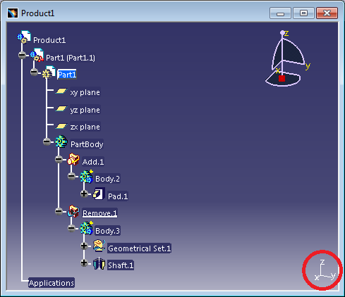
Tinkering with it I notice that it does not see Part workbench solids a linkable.
If the source file has a Body, it shows it available for linking. If the source file has a Part (Std_Part), it shows it available for linking. If the source file has a Part Cut, Extrude, etc., it is not available for linking.
I realize it is very early in development, but figured I'd point this out.
Posted about this in the forum: https://forum.freecad.org/viewtopic.php?t=81311
Full version info
Subproject(s) affected?
None
Anything else?
No response
Code of Conduct