 vostrenkov
commented
4 years ago
vostrenkov
commented
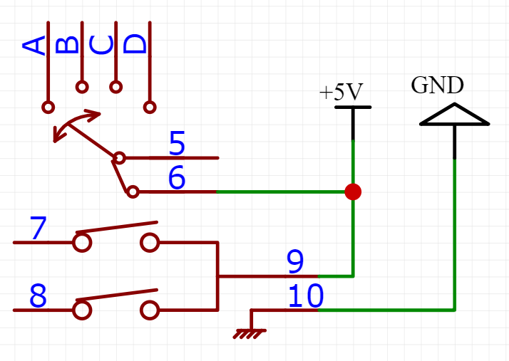
4 years ago Hi, I don't see a reason it should not work here. You dont even need external pulling resistors, bluepill provides internal pull-ups and pull-downs. Just connect terminals as ordinary buttons (Button VCC or Button GND) and set encoder inputs as Encoder A and B, buttons inputs as Button Normal or whatever you need
 jieweiyang
 0xcore
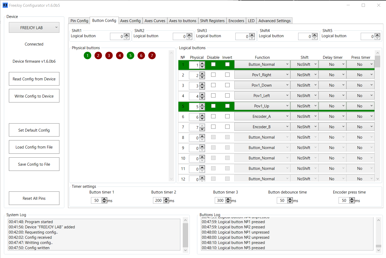

 0xfgarcia
 AndyPeacock
 geologic
Hi,
Does anyone know if it is possible to use with Freejoy ?
https://tech.alpsalpine.com/prod/e/html/multicontrol/switch/rkjxt/rkjxt1f42001.html
I have seen that it is possible with Arduino & Teensy but I suppose it would need some modification to work with FreeJoy.
Arduino https://github.com/darjusp/test
Teensy https://www.xsimulator.net/community/threads/teensy-lc-arduino-scripts.9681
Thanks!