GaudiLabs / OpenLaserScanningMicroscope

Open Source Laser Scanning Microscope
GNU General Public License v3.0
314 stars 34 forks source link

Could electronics schmatic will be more clear? #1

Open Retro-Fitt opened 3 years ago

Retro-Fitt commented 3 years ago

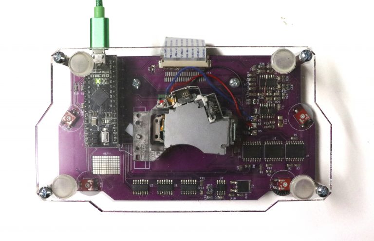
Hi, Very cool project! Could component valules be more clear?

For example: R2 180k or 270k R32 6.8k or 68k C4 100nf or 1nf Is Q1 LR120N There are 3 different BOM lists.Which one is correct?

Is SEL1 SEL2 LASER will be selected from Jumper 1? resim

2.1v +/-0.1v is this vref?or U13D pin number 12 value? resim

What are the values top of pdf?: resim

How can we set these diode currents? resim

Where these stuff connects? resim

Thank you very much in advance!

GaudiLabs commented 3 years ago

Hi

Happy to hear your into DVD Laser scanner.

Most recent BOM is "Bill of Materials (BOM) DVD Laser Scanner V2" Values in Schematic should be correct. The blue texts are just notes I made during the design, you can ignore them.

Laser can be selected from software.

2.1v +/-0.1v is this vref? AND U13D pin number 12 value. (Voltage follower)

Values are deflection in mm of DVD coil for different DVD heads... again, just ignore.

Diode currents are set by DVD head electronic.

The project is work in progress and I stopped working on it. So please take as is.

Best, Urs

Retro-Fitt commented 3 years ago

Hi again, Many thanks for your reply. I liked it very much and i will use as silicon chip inspection and some electronic parts inspection mostly.I will not use for microbiological stuff. I have already made PCB in china with jlcpcb, its in shipping now.I have used your github gerber files to made PCB. resim resim I couldn't find exact file name as "Bill of Materials (BOM) DVD Laser Scanner V2" I have cloned your github as zip and unzipped it. resim It doesn't matter much for me now because i ordered all 3 of them and also checked schmatic and compared all components :) But maybe sometime later some guy like me wanted to build this.

"Values in Schematic should be correct. The blue texts are just notes I made during the design, you can ignore them." I just want to be sure, i assume this is the correct schematic right?I will ignore blue text debug stuff that you made. DVDLaserScannerII.pdf

Also Q1 pin number 2 (i_laser) is not connected to anywhere.Is Q1 required really?Or you are using it as a diode?

"Diode currents are set by DVD head electronic." Oh i see, there are 3 trimmers i think.I also buy it from aliexpress can't check it for now.Any recommendation to calibrate this?I don't want to ruin diodes.

What does J1 used for?I assume its for debugging stuff.Also i assume Vref1 F1 T1 also seems for debugging stuff.Any recommendations for calibrating these values?

"The project is work in progress and I stopped working on it. So please take as is." No problem at all.I love troubleshooting and making diy electronics stuff.

Again many many thanks for your reply.

pieroantonio commented 1 year ago

Dear @bra1nslayer did you then manage to build one? I am approaching construction for biological studies. If you have built one, would you like to hear us to see the problems and maybe continue with the development?

Retro-Fitt commented 1 year ago

@pieroantonio

I am suprised that someone like me have interest in this project.

I get all pcb and parts for it but never build one because it required 2 laser modules. I realised that fact in when original author is revised and uploaded new photos of microscope.

Sadly i lost interest because finding laser module and investing was not suitable anymore. Also as you might know it is not a finished project and troubleshooting will be a pain and hard to understand.I haven't heard any news from author as you can see above.

Long story short i couldn't get another laser module for it and i don't know if it works with only one PHR-803T, as i mentioned above you need two of them.Maybe one PHR-803T and some generic laser module works fine i don't know.

Any suggestions are welcome.

pieroantonio commented 1 year ago

Hello how nice to finally find someone else interested in this project. In my opinion it is a nice project and could have interesting applications, too bad it was abandoned. I ordered the laser modules from aliexpress. https://a.aliexpress.com/_Ewalq1N In the weekend I will try to assemble everything and I hope that the instructions are quite detailed. Do you have any suggestions?

Il gio 6 ott 2022, 20:34 bra1nslayer @.***> ha scritto:

@pieroantonio https://github.com/pieroantonio

I am suprised that someone like me have interest in this project.

I get all pcb and parts for it but never build one because it required 2 laser modules. I realised that fact in when original author is revised and uploaded new photos of microscope.

Sadly i lost interest because finding laser module and investing was not suitable anymore. Also as you might know it is not a finished project and troubleshooting will be a pain and hard to understand.I haven't heard any news from author as you can see above.

Long story short i couldn't get another laser module for it and i don't know if it works with only one PHR-803T, as i mentioned above you need two of them.Maybe one PHR-803T and some generic laser module works fine i don't know.

Any suggestions are welcome.

— Reply to this email directly, view it on GitHub https://github.com/GaudiLabs/OpenLaserScanningMicroscope/issues/1#issuecomment-1270517546, or unsubscribe https://github.com/notifications/unsubscribe-auth/AF33UQGGSNL5X7WX5PRD4UTWB4LTBANCNFSM4WH34NWQ . You are receiving this because you were mentioned.Message ID: @.***>

pieroantonio commented 1 year ago

What are the four variable resistors for? And then you would need the stl files for the pickup supports.

Il gio 6 ott 2022, 22:22 Piero Antonio Zecca @.***> ha scritto:

Hello how nice to finally find someone else interested in this project. In my opinion it is a nice project and could have interesting applications, too bad it was abandoned. I ordered the laser modules from aliexpress. https://a.aliexpress.com/_Ewalq1N In the weekend I will try to assemble everything and I hope that the instructions are quite detailed. Do you have any suggestions?

Il gio 6 ott 2022, 20:34 bra1nslayer @.***> ha scritto:

@pieroantonio https://github.com/pieroantonio

I am suprised that someone like me have interest in this project.

I get all pcb and parts for it but never build one because it required 2 laser modules. I realised that fact in when original author is revised and uploaded new photos of microscope.

Sadly i lost interest because finding laser module and investing was not suitable anymore. Also as you might know it is not a finished project and troubleshooting will be a pain and hard to understand.I haven't heard any news from author as you can see above.

Long story short i couldn't get another laser module for it and i don't know if it works with only one PHR-803T, as i mentioned above you need two of them.Maybe one PHR-803T and some generic laser module works fine i don't know.

Any suggestions are welcome.

— Reply to this email directly, view it on GitHub https://github.com/GaudiLabs/OpenLaserScanningMicroscope/issues/1#issuecomment-1270517546, or unsubscribe https://github.com/notifications/unsubscribe-auth/AF33UQGGSNL5X7WX5PRD4UTWB4LTBANCNFSM4WH34NWQ . You are receiving this because you were mentioned.Message ID: @.***>

Retro-Fitt commented 1 year ago

I believe pots are for focus and laser output.You can look Arduino code.I might assemble board and try with another laser module assembly for lens moving coils.

I can assemble board next week.

pieroantonio commented 1 year ago

it would be great to reactivate this project. I am a university researcher who deals with morphology and having this tool to accompany my Sem would be magnificent.

Il gio 6 ott 2022, 23:03 bra1nslayer @.***> ha scritto:

I believe pots are for focus and laser output.You can look Arduino code.I might assemble board and try with another laser module assembly for lens moving coils.

I can assemble board next week.

— Reply to this email directly, view it on GitHub https://github.com/GaudiLabs/OpenLaserScanningMicroscope/issues/1#issuecomment-1270695976, or unsubscribe https://github.com/notifications/unsubscribe-auth/AF33UQAUIRHWGPOGD3FWHXTWB45DJANCNFSM4WH34NWQ . You are receiving this because you were mentioned.Message ID: @.***>

pieroantonio commented 1 year ago

Actually the variable resistances I thought to mount them outside the pcb because the micro movements of adjustment could move the sample.

Il gio 6 ott 2022, 23:08 Piero Antonio Zecca @.***> ha scritto:

it would be great to reactivate this project. I am a university researcher who deals with morphology and having this tool to accompany my Sem would be magnificent.

Il gio 6 ott 2022, 23:03 bra1nslayer @.***> ha scritto:

I believe pots are for focus and laser output.You can look Arduino code.I might assemble board and try with another laser module assembly for lens moving coils.

I can assemble board next week.

— Reply to this email directly, view it on GitHub https://github.com/GaudiLabs/OpenLaserScanningMicroscope/issues/1#issuecomment-1270695976, or unsubscribe https://github.com/notifications/unsubscribe-auth/AF33UQAUIRHWGPOGD3FWHXTWB45DJANCNFSM4WH34NWQ . You are receiving this because you were mentioned.Message ID: @.***>

Retro-Fitt commented 1 year ago

Yes using external pots would be logical for not moving sample. Already then, i will assemble board next week.We can debug together.

pieroantonio commented 1 year ago

I started to assemble the dear components. I got the shopping list wrong because I saw the bom file and not the last pdf. So now I have to order other components and wait for them to arrive. Meanwhile, I have some questions: Is C4 100nf or 1 nf? Is C11 missing? What transistor do you need on Q1? Is the jp1 jumper ultimately a selector of the type of laser used? If you then I can mount it external.

I designed a container to print, in the afternoon I put it in print and let you know. I wanted to mount both on the container and on the container an RJ45 female for convenience.

Il ven 7 ott 2022, 05:51 Piero Antonio Zecca @.***> ha scritto:

Of course perfect maybe in two we can better make it work

Il gio 6 ott 2022, 23:20 bra1nslayer @.***> ha scritto:

Yes using external pots would be logical for not moving sample. Already then, i will assemble board next week.We can debug together.

— Reply to this email directly, view it on GitHub https://github.com/GaudiLabs/OpenLaserScanningMicroscope/issues/1#issuecomment-1270711404, or unsubscribe https://github.com/notifications/unsubscribe-auth/AF33UQDOWA23GXS5NLVFN3TWB47DFANCNFSM4WH34NWQ . You are receiving this because you were mentioned.Message ID: @.***>

pieroantonio commented 1 year ago

this is the cover that I design and print. cover v2.zip

GaudiLabs commented 1 year ago

Happy to see you guys exploring the project. Good to have a cover. Values in Schematic should be correct.

GaudiLabs commented 1 year ago

More discussions and information here on the forum: https://forum.hackteria.org/t/laser-optical-pickup-unit-hacking/771/49

pieroantonio commented 1 year ago

Of course perfect maybe in two we can better make it work

Il gio 6 ott 2022, 23:20 bra1nslayer @.***> ha scritto:

Yes using external pots would be logical for not moving sample. Already then, i will assemble board next week.We can debug together.

— Reply to this email directly, view it on GitHub https://github.com/GaudiLabs/OpenLaserScanningMicroscope/issues/1#issuecomment-1270711404, or unsubscribe https://github.com/notifications/unsubscribe-auth/AF33UQDOWA23GXS5NLVFN3TWB47DFANCNFSM4WH34NWQ . You are receiving this because you were mentioned.Message ID: @.***>

pieroantonio commented 1 year ago

in position Q1 I think a mosfet should go. which one do you recommend?

Retro-Fitt commented 1 year ago

@pieroantonio i believe its LR120N.But in my PCB one pin of mosfet goes nowhere:) i will check tomorrow.

pieroantonio commented 1 year ago

exactly, the transistor pad 2 doesn't go anywhere. I've assembled all the smd components i just need to install the 2 tlc2274. then i need to find out where to solder the 3 wires (REF, F1 and T1) to the lower DVD pick up. How are you with assembly?

Retro-Fitt commented 1 year ago

i didn't have spare time to build sadly.waiting to have some holiday.

timokruck commented 1 year ago

Hey, I also recently got interested int he project, and face the same issue with the drain of the transistor not connecting anywhere. Neither in the PCB, nor does "I_LASER" connect to anywhere in the schematics. In the pictures on the website : "https://www.gaudi.ch/GaudiLabs/wp-content/uploads/DVDLaserScannerBottom-768x494.jpg" there is also no extra connection to it. Has anyone of you gotten forward with it?

GaudiLabs commented 1 year ago

Hey, I also recently got interested int he project, and face the same issue with the drain of the transistor not connecting anywhere. Neither in the PCB, nor does "I_LASER" connect to anywhere in the schematics. In the pictures on the website : "https://www.gaudi.ch/GaudiLabs/wp-content/uploads/DVDLaserScannerBottom-768x494.jpg" there is also no extra connection to it. Has anyone of you gotten forward with it?

Guess I added the current controller with Q1 to connect a pick-up laser diode directly (by a wire to the gate). If the intensity can be controlled directly trough the pick-up connector (U11) then Q1 is not needed.

pieroantonio commented 1 year ago

another infrmation but the pickup below is connected to the pcb with 3 wires, these wires where should be connected on the pickup?

GaudiLabs commented 1 year ago

another infrmation but the pickup below is connected to the pcb with 3 wires, these wires where should be connected on the pickup?

The pick-up below only serves for left-right / up-down movement. The wires need to be connected to the corresponding coils on the pick-up.

NilanEkanayake commented 1 year ago

In the pdf, why are VREF1 and VREF2 the same voltage? Is the current through both pickups too much for one op amp to handle?

Also, if like me you're having trouble sourcing cheap TCA0372s, they seem to be interchangeable (same pinout, same specs) with NCS2372 or NCV0372 (and potentially L2720W, same pinout slightly different specs)

pieroantonio commented 1 year ago

Finally I finished assembly and testing. I have two problems: the lower pickup unlike the upper one does not perform any scan movement; and the second problem is that the sensor does not acquire any images. How can I fix?

NilanEkanayake commented 1 year ago

Finally I finished assembly and testing. I have two problems: the lower pickup unlike the upper one does not perform any scan movement; and the second problem is that the sensor does not acquire any images. How can I fix?

You'll need to probe around on the PCB, likely with an oscilloscope, to see if there's any signal going to the bottom coil, or any leaving the MCP4922 for that channel.

As for the sensor, pretty similar story. Probe and see if you're getting the correct signals from the PDIC (should be somewhere around 0.5v peak to peak when looking at a blank DVD? I haven't personally used this OPU) and that the PDIC is also getting the correct reference voltage and power.

It's probably not a one-click-fix.

nup002 commented 1 year ago

With the apparent renewed interest in this topic, I think that updating this repository with fixes for the issues discovered in this thread would be appreciated by the maker community @GaudiLabs . I am personally interested in taking this project further, but I need a solid base to start from.

timokruck commented 1 year ago

What do you intend to do? What do you need? This project is already a very solid base imo. I've assembled it and it works quite nice with the provided code for what it wants to do. My biggest problem getting it to work was a broken ffc cable tbh.

nup002 commented 1 year ago

I agree that this design is a perfect launcing pad, and will save me many hours. I intend to first build one for myself, to get a feel for how Gaudi's design works and to use it as a dev board. With his permission I intend to make improvements to the design if possible, polish up the schematic and BOM, write manuals and documentation, create an assembly video, all to make it more accessible to the maker community. I think with a bit of extra work it could be an excellent low-cost project for beginners in the maker scene or for science classes in school.

I just have a few questions to help me understand his schematic.

  1. POT1, POT2, POT3, and POT4 appear unused. Do you remember what their intended purpose was?
  2. Why did you create two independent VREF1 and VREF2 for the two OPUs?
  3. VREF_DAC does not appear to have a source. Is it misnamed?
  4. PD_RF appears unused. Do you remember what its intended purpose was?
timokruck commented 1 year ago

That's a good idea I guess, altough I don't know if SMD soldering is accessible for a school project.

  1. The potentiometers are used in the software for controlling the coils and the laser intensity of the OPU. But if you rewrite the software you can obviously also controll it without the potentiometers making them obsolete. There are also some other irritating lines in the code. For example of the top of my head one calculation always returns a 0 and there is a self-written SPI inside..
  2. I don't know. But they seem to be the same, I haven't measured it yet while in operation.
  3. Not sure right now.
  4. It's used to read out the 43, or 44 pin (chosen by the jumper) of the OPU. As I said I have written my own software using the given hardware from the ground up for my purposes and haven't used it yet, so I don't exactly know what's behind the pins 43 and 44 of the OPU, but it would be nice to figure that out.
NilanEkanayake commented 1 year ago

@nup002 I've been doing the same thing myself. I designed my own lower-cost board that can be printed and assembled very cheaply by JLCPCB once you get the $2 for 5 boards deal and all the assembly coupons (came to $10 US plus a couple parts that I ordered from LCSC).

It's possible to have a board that can be fabricated and assembled in its entirety by JLCPCB for less than $15-20, or $3-4 per board.

Here's my design: https://github.com/NilanEkanayake/LaserScanningMicroscope

However it's more an experiment and has a lot of issues, as well as no stand to hold the pickups.

Once I finish testing my current design, I'll make a V2 that fixes the issues and swaps out the STM32G473 for a cheaper chip that uses PWM + a filter instead of DACs.

nup002 commented 1 year ago

That is interesting @NilanEkanayake, very cheap! Any timeline on V2?

NilanEkanayake commented 1 year ago

That is interesting @NilanEkanayake, very cheap! Any timeline on V2?

It'll be a few months. The to-do list is pretty long.

ProfesorMoriartiX commented 4 months ago

Muy buenas tardes @GaudiLabs , ensamble el microscopio y estas son las primeras imágenes. Es normal la formación de la cruz? note que la línea horizontal se da cuando el lector inferior se mueve. Se debe esperar un tiempo para la captura de imágenes? hay una distancia máxima entre la muestra y el lector? Te agradezco mucho por tu tiempo y a la espera de tus consejos. LaserDump 2024_04_19_17_23_56 LaserDump 2024_04_19_23_40_14

Rushabh-parth commented 4 months ago

Hii @ProfesorMoriartiX are you working from this @GaudiLabs given schematic and pcb design or you made your own ? because i want to start this project but don't know where to start and what things come in challenge. can i contact you ?

NilanEkanayake commented 4 months ago

I made my own version, found here: https://github.com/NilanEkanayake/LaserScanningMicroscope

There's more details further up in the thread