 IanSB
commented
2 months ago
IanSB
commented
2 months ago @dadecoza
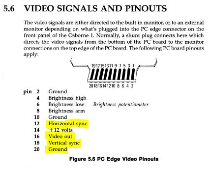
According to the manual you linked, the actual crystal frequency is 15.9744Mhz:
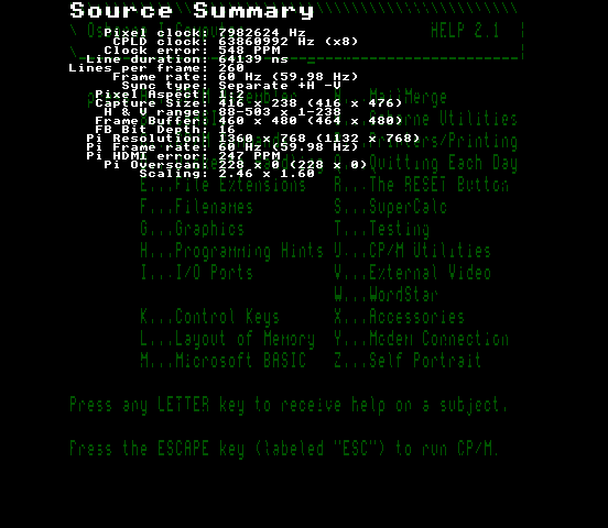
So the "8" Mhz dot clock is 7987200 not 8000000 which might fix the mis-sampling but it looks like the image is shifted which can happen if the Hsync is wider than than the blanking period and not a normal hsync. After tweaking the clock, can you post screencaps of the source summary page in the info menu and the geometry and sampling menus. Press the Up and Down buttons together to screencap a menu, files in /captures on the SD card
 dadecoza
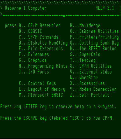
I'm having an issue creating a custom profile,
According to the Osborne 1 Technical Manual the settings should be as follows ...
Width in pixels: 416 Height in pixels: 240 Dot clock: 8Mhz
However the output I get looks like ...
Any tips?
Thanks!