JeremyGrosser / rp2040_hal

Ada drivers for the Raspberry Pi RP2040 SoC
https://pico-doc.synack.me/
BSD 3-Clause "New" or "Revised" License
38 stars 11 forks source link

I2C: 16bit EEPROM adresses are split on the SECOND read #49

Open hgrodriguez opened 1 year ago

hgrodriguez commented 1 year ago

I2C: 16bit EEPROM adresses are split on the SECOND read

Hi Jeremy, I spent some time investigating my code and could not find the problem. Then I came back to your code and adjusted it a little bit to enable me to debug it better. I do appreciate, that you do not have time to resolve this soon, I just wanted to make sure that I used your code (not mine) to reproduce it. Let me know, if I did something wrong.

I have this in my alire.toml: [[depends-on]] pico_bsp = "^2.0.0"

See code below:

with RP.Device;
with RP.Clock;
with RP.GPIO;
with RP.I2C_Master;
with Pico;
with HAL.I2C;
with HAL; use HAL;

procedure Jeremy is
   use RP.GPIO;
   use HAL.I2C;

   SCL  : GPIO_Point renames Pico.GP15;
   SDA  : GPIO_Point renames Pico.GP14;
   Port : RP.I2C_Master.I2C_Master_Port renames RP.Device.I2CM_1;
   Addr : constant I2C_Address := 2#1010_000_0#;

   --------------------------------------------------------------------------
   --  HOLGER: make the size of the array adjustable
   ARRAY_SIZE : constant Integer := 1;

   --------------------------------------------------------------------------
   --  HOLGER: add array for Writing
   Data_W     : I2C_Data (1 .. ARRAY_SIZE) := (others => 0);

   --------------------------------------------------------------------------
   --  HOLGER: add array for Reading
   Data_R     : I2C_Data (1 .. ARRAY_SIZE);

   Status     : I2C_Status;
begin
   RP.Clock.Initialize (Pico.XOSC_Frequency);
   RP.Clock.Enable (RP.Clock.PERI);
   Pico.LED.Configure (Output);
   Pico.LED.Set;

   SCL.Configure (Output, Pull_Up, RP.GPIO.I2C, Schmitt => True);
   SDA.Configure (Output, Pull_Up, RP.GPIO.I2C, Schmitt => True);
   Port.Configure (Baudrate => 400_000);

   RP.Device.Timer.Enable;

   --------------------------------------------------------------------------
   --  HOLGER: complete loop unrolling to focus on the problem
   --          and make debugging easier

   --------------------------------------------------------------------------
   --  HOLGER: Case Data_W (1) := 1
   Data_W := (others => Data_W (1) + 1);
   Port.Mem_Write
     (Addr          => Addr,
      Mem_Addr      => 0,
      Mem_Addr_Size => Memory_Size_16b,
      Data          => Data_W,
      Status        => Status,
      Timeout       => 1000);
   if Status = Ok then
      Pico.LED.Set;
   end if;
   RP.Device.Timer.Delay_Milliseconds (500);

   Port.Mem_Read
     (Addr          => Addr,
      Mem_Addr      => 0,
      Mem_Addr_Size => Memory_Size_16b,
      Data          => Data_R,
      Status        => Status,
      Timeout       => 1000);
   if Status = Ok then
      Pico.LED.Set;
   end if;
   RP.Device.Timer.Delay_Milliseconds (500);

   --------------------------------------------------------------------------
   --  HOLGER: compare the array written with the array read
   for I in 1 .. ARRAY_SIZE loop
      if Data_W (I) /= Data_R (I) then
         --------------------------------------------------------------------
         --  Holger: STOP if data different: it is the same
         Pico.LED.Clear;
         loop
            null;
         end loop;
      end if;
   end loop;

   --------------------------------------------------------------------------
   --  HOLGER: Case Data_W (1) := 2
   Data_W := (others => Data_W (1) + 1);
   Port.Mem_Write
     (Addr          => Addr,
      Mem_Addr      => 0,
      Mem_Addr_Size => Memory_Size_16b,
      Data          => Data_W,
      Status        => Status,
      Timeout       => 1000);
   if Status = Ok then
      Pico.LED.Set;
   end if;
   RP.Device.Timer.Delay_Milliseconds (500);

   Port.Mem_Read
     (Addr          => Addr,
      Mem_Addr      => 0,
      Mem_Addr_Size => Memory_Size_16b,
      Data          => Data_R,
      Status        => Status,
      Timeout       => 1000);
   if Status = Ok then
      Pico.LED.Set;
   end if;
   RP.Device.Timer.Delay_Milliseconds (500);

   --------------------------------------------------------------------------
   --  HOLGER: compare the array written with the array read
   for I in 1 .. ARRAY_SIZE loop
      if Data_W (I) /= Data_R (I) then
         --------------------------------------------------------------------
         --  Holger: STOP if data different -> it *is* different!
         Pico.LED.Clear;
         loop
            null;
         end loop;
      end if;
   end loop;

   --------------------------------------------------------------------------
   --  HOLGER: we end here if everything is OK
   loop
      Pico.LED.Set;
   end loop;

end Jeremy;

I used GDB to step through the program, but the same behaviour is true if run as normal without debugger attached.

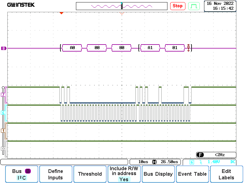
Those are the results: Write Data=1 -> OK Write Data=1 -> OK
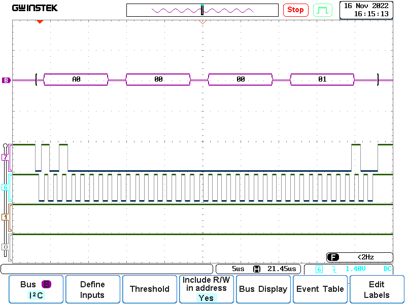
Read Data=1 -> OK Read Data=1 -> OK

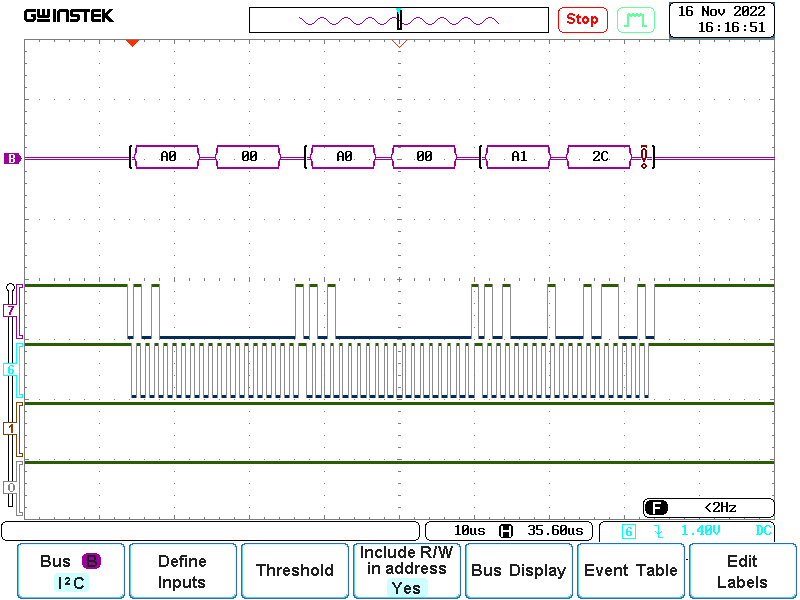
Write Data=2 -> OK Write Data=2 -> OK
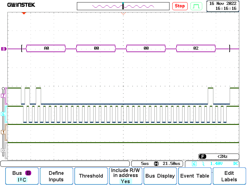
Read Data=2 -> NOK Read Data=2 -> NOK
JeremyGrosser commented 1 year ago

I have a fix, but I'm afraid it might break other I2C devices. Please test out the https://github.com/JeremyGrosser/rp2040_hal/tree/issue_49 branch and let me know if it solves your problem.

hgrodriguez commented 1 year ago

Thanks I will look at it as early as I can. Currently my work bench has another project so maybe next weekend

hgrodriguez commented 1 year ago

i checked and the behaviour did not improve, same separation of the address still there. When I remember correctly, pico_bsp 1.6.0 worked fine with 16 bit addresses, not sure what you changed in the i2c code. I will try to spend more time, but at the moment I have a different project going.

hgrodriguez commented 1 year ago

I had some time to debug in the libraries. I am not sure, if this helps, what I write below. My view is, that if I call a procedure multiple times with the very same parameters, then the behaviour should be the same. I found the following using the code above.

The first time I call Port.Mem_Write on line 49, I found out, that in the procedure RP.I2C.Write the flags for:

P.IC_DATA_CMD :=
         (RESTART => (if This.Repeated_Start and P.IC_DATA_CMD.FIRST_DATA_BYTE = ACTIVE then ENABLE else DISABLE),
          STOP    => (if not This.Repeated_Start and This.TX_Remaining = 1 then ENABLE else DISABLE),
          CMD     => WRITE,
          DAT     => Data,
          others  => <>);

result in:

P.IC_DATA_CMD :=
         (RESTART => DISABLE,
          STOP    => DISABLE,
          CMD     => WRITE,
          DAT     => Data,
          others  => <>);

The second time I call Port.Mem_Write on line 89, I found out, that in the procedure RP.I2C.Write the flags for:

P.IC_DATA_CMD :=
         (RESTART => (if This.Repeated_Start and P.IC_DATA_CMD.FIRST_DATA_BYTE = ACTIVE then ENABLE else DISABLE),
          STOP    => (if not This.Repeated_Start and This.TX_Remaining = 1 then ENABLE else DISABLE),
          CMD     => WRITE,
          DAT     => Data,
          others  => <>);

result in:

P.IC_DATA_CMD :=
         (RESTART => ENABLE,
          STOP    => DISABLE,
          CMD     => WRITE,
          DAT     => Data,
          others  => <>);

As written above, not sure if this helps, but even having the very same parameters in both calls, I would not expect, that those flags are different. Maybe this is a hint for you.

hgrodriguez commented 1 year ago

I would like to offer to send you EEPROMS like the ones I use: https://www.mouser.com/ProductDetail/Microchip-Technology/24FC64F-I-P?qs=WqWCsLCZBkoe3htI4nCQOg%3D%3D and ship it to your private address if this helps to debug. Let me know.

JeremyGrosser commented 1 week ago

I believe I've fixed the behavior of RP.I2C_Master with release 2.4.0. Sorry it took so long.