JustinSDK
commented
5 years ago
JustinSDK
commented
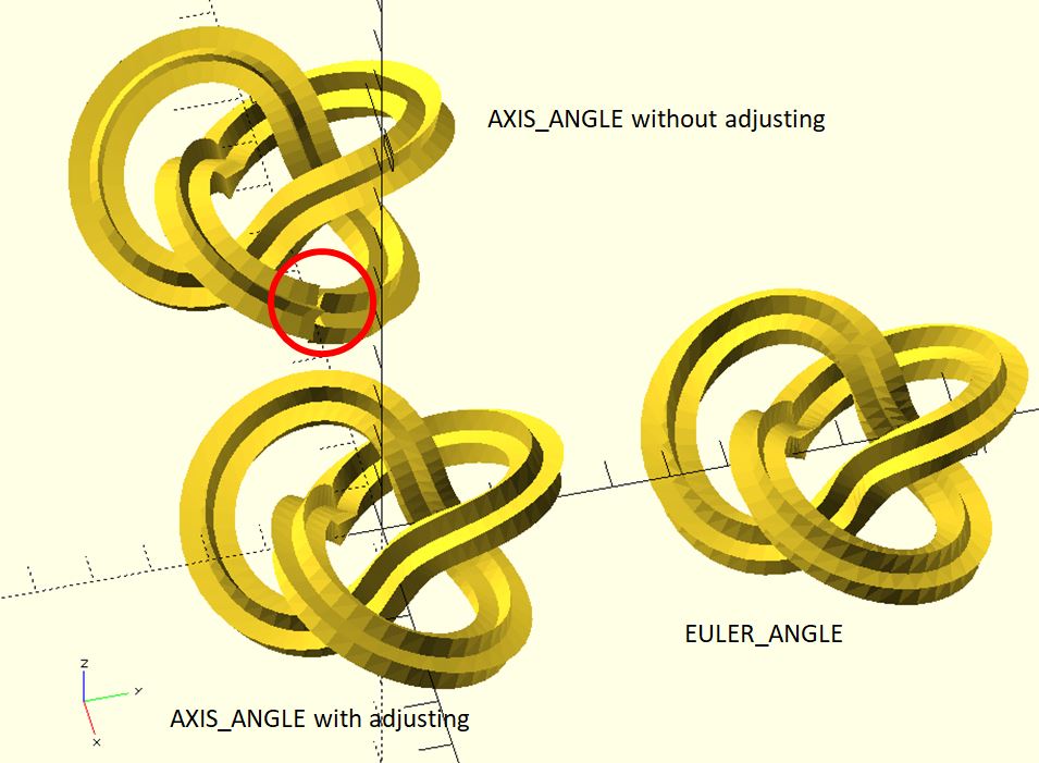
5 years ago Actually, it's correct behavior of path_extrude in dotSCAD 1.1 or later because it takes different algorithm for rotating sections from path points.
If you want to extrude a shape along a path precisely, providing enough information about how to rotate sections is necessary. If you want to extrude a shape along a helix, helix_extrude is more suitable because it knows how to dig out necessary data for rotating sections precisely.
include <rotate_p.scad>;
include <polysections.scad>;
include <helix.scad>;
include <cross_sections.scad>;
include <helix_extrude.scad>;

r = 10;
fa = 2;

shape_pts = [
    [0,0],
    [-3, 1],
    [0, 2]
];

$fn = 360 / fa;

helix_extrude(
    shape_pts,
    radius = r,
    levels = 5,
    level_dist = 3.6,
    vt_dir = "SPI_UP"
);
If you have only points, what path_extrude can do is to guess data about rotations. The different algorithm will dig out different data. path_extrude in dotSCAD 1.0 just has the result you want but has an obvious bug in some situation. (See issue #3). The bug is fixed after v1.1.
If you still want to use path_extrude, one way to get what you want is using the twist parameter. For example:
include <rotate_p.scad>;
include <polysections.scad>;
include <path_extrude.scad>;

r = 10;
fa = 2;

shape_pts = [
    [0,0],
    [3, 1],
    [0, 2]
];

path_pts = [
    for(a = [0:fa:360 * 5])
    [-r * cos(a), r * sin(a), a/100]
];

path_extrude(
    shape_pts,
    path_pts,
    twist = 100 // adjust it
);
In this situation, you provide information which path points do not provide. You think it's a bug in path_extrude after dotSCAD 1.1 because your brain has information that path points do not provide.
(Even though old algorithm of path_extrude has an obvious bug, it has some benefits in some situations. I'm still considering whether I should provide an option for users to switch these two algorithms in the later version.)

 chill1n


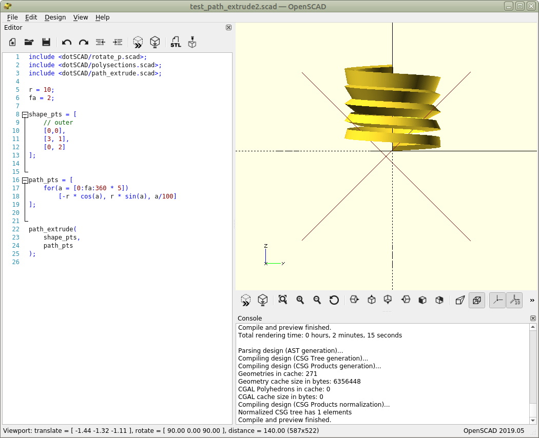
Instead of a regular thread, I see a gradually rotated thread for increasing z. With release v1.0.0 the behavior was correct, but with release v1.2.0 (and possibly older releases) the behavior is incorrect. The code that shows this behavior is:
include <dotSCAD/rotate_p.scad>; include <dotSCAD/polysections.scad>; include <dotSCAD/path_extrude.scad>;
r = 10; fa = 2;
shape_pts = [ // outer [0,0], [3, 1], [0, 2] ];
path_pts = [ for(a = [0:fa:360 5]) [-r cos(a), r * sin(a), a/100] ];
path_extrude( shape_pts, path_pts );
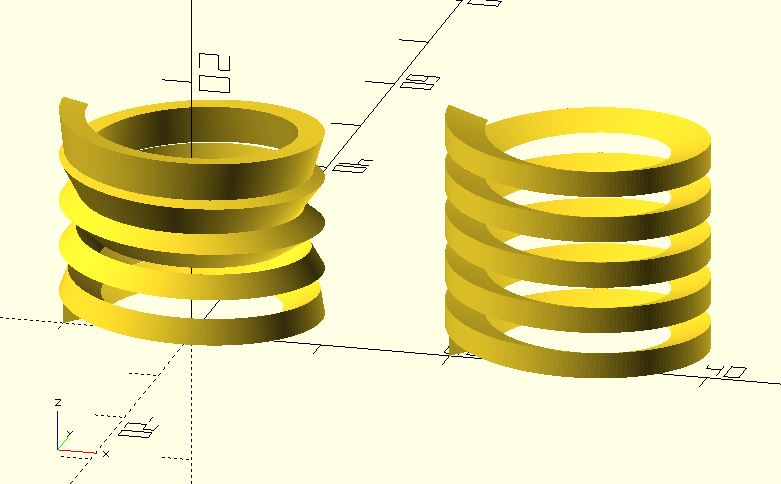
The correct output result is shown below.
The incorrect output result is shown below.