 rohinrohin
commented
11 months ago
rohinrohin
commented
11 months ago @vaidehi-joshi the "Collision Detected, waiting to send packet" means that the red signal wire has been pulled low when the TX line is wanting to transmit. As it is half duplex, you cannot transmit whilst the red wire has been pulled low.
You should never see the collision message. Since I've had the PCB working, I have never seen it.
Thanks for that, my unit is one of these ones
You didn't attach an image. What model GDO do you have? Please check Paul Wieland's Wiki article on supported models. Yours might be Security+ 1.0. https://github.com/PaulWieland/ratgdo/wiki
If yours is Security+ 1.0 you won't be able to use ESPHome and will have to run native ratgdo.
For Security+ 1.0 you apparently must use the D1, D2, D7 pin layout (not D2, D4, D7).

Sorry for being MIA! Thanks a ton @Kaldek, @rlowens, @sanjay900 for your updates.
This is possible the issue, I have confirmed that we are indeed on Security+ 1.0, will loop back here once we verify with the native firmware.
Once done, @vaidehi-joshi and I will summarize all of our learnings till now (including compiling with ESPHome, Security.., and many other nuances that we came across).
 sanjay900
 ccutrer
 Kaldek
 vaidehi-joshi
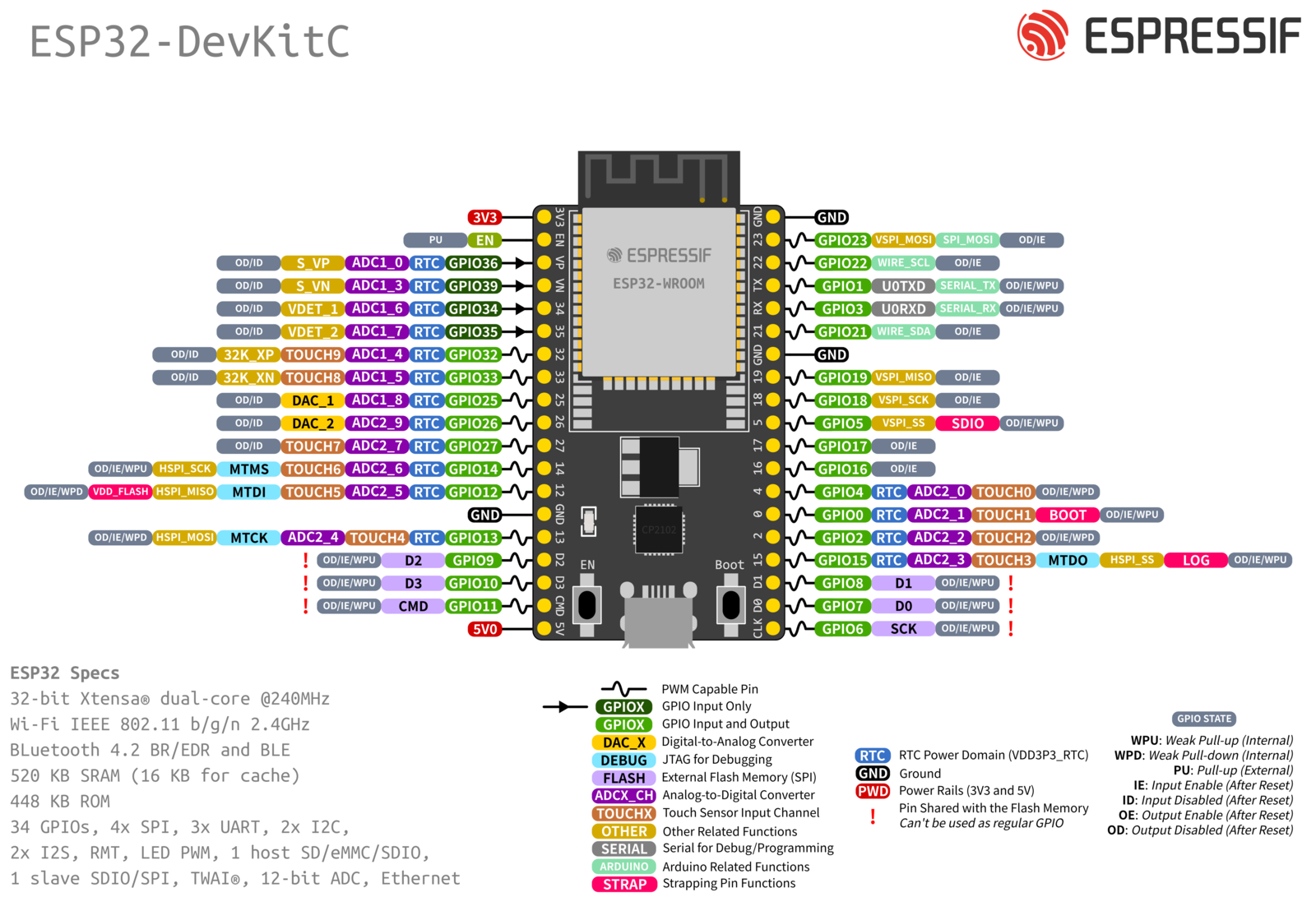
Hey @Kaldek!
Great job on this repo and for constantly updating the instructions! I am in process of setting this up and would appreciate your help on this.
I have a ESP WROOM 32, pinout here. (sorry about the amazon links)
I was wondering if there were any nuances that would make my installation steps a bit different?
I noticed on the pinout of this board vs the D1 mini
I was curious if I was on the right track with the pinout mapping and how this changes things. Also side note, I was not able to find the IRL mosfet easily, have ordered it but I am using the 2n7000 for now.
Thanks and looking forward to your response!