 KevinOConnor
commented
1 year ago
KevinOConnor
commented
1 year ago Unfortunately there isn't sufficient information to provide much assistance.
Error reports from other devices don't necessarily indicate a problem. It's common for CANbus chips to transition to an "error passive" state when the bus first comes up - the chip may need to observe a few dozen normally transmitted packets before it will stop reporting errors (that is, it transitions back to an "error active" state).
If you're still seeing errors after a prolonged period, you should try with known working software. You can use the Klipper software in "USB to canbus" mode to test with ( https://github.com/KevinOConnor/can2040/blob/master/docs/Tools.md ).
If you continue to see errors while using the Klipper software then it will be necessary to take captures of the low-level signalling to find out the actual source of the problem. A logic analyzer can be used for this purpose ( https://github.com/KevinOConnor/can2040/blob/master/docs/Tools.md ).
-Kevin
 JamesWGT3


Thank you for this amazing library - it's a game changer for me with this processor.
I am using the arduino wrapper version of this library for clarity.
I seem to be getting error frames after virtually every Tx from BusMaster to the device. The data is received by the RP2040 fine, so there is no issue there, but the error flags are being raised, which will cause issues if it was added to a bigger bus - this doesn't happen with exactly the same set up, but exchanging the RP2040 for a teensy 4.1 and using FlexCANT4.
The set up/config I am using is as follows;
Sender: Busmaster -> Peak CAN FD, 1MBaud -> 120Ohm terminator Receiver: 120Ohm terminator -> SN65HVD Transceiver -> Pi Pico pins 18RX, 19TX
The errors apear after a single send, as well as with cyclic transmissions and seems to cause timing issues with the send on cyclic.
Single Send;
Cyclic 10ms Send;
Sending from the device seems to be ok, with perfect timing on the cyclic send;
Single Send;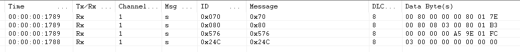
Cyclic 10ms Send;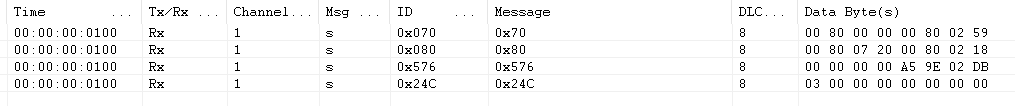
Please let me know if there is any more information I can collect for this issue to resolve it - thank you again!
Edit: I updated the ACAN2040 library can2040.h and can2040.c files to your latest, using the following wrapper in ACAN2040.h to remove compilation errors for the IRQ handling, but still have the same issues when sending to the RP2040 from another device.
`extern "C" {
include "can2040.h"
}`