Closed bdn76 closed 5 years ago
Hi @bdn76,
It did not look like there was a Klipper log file attached to this ticket. The log file has been engineered to answer common questions the Klipper developers have about the software and its environment (software version, hardware type, configuration, event timing, and hundreds of other questions).
Unfortunately, too many people have opened tickets without providing the log. That consumes developer time; time that would be better spent enhancing the software. If this ticket references an event that has occurred while running the software then the Klipper log must be attached to this ticket. Otherwise, this ticket will be automatically closed in a few days.
For information on obtaining the Klipper log file see: https://github.com/KevinOConnor/klipper/blob/master/docs/Contact.md
The log can still be attached to this ticket - just add a comment and attach the log to that comment.
Best regards, ~ Your friendly GitIssueBot
PS: I'm just an automated script, not a human being.
@bdn76 Take a look to the datasheets. Registers are similar to 2130. The default contents not.
It's fine if someone wishes to add spi support for the tmc5160. It does require some host python development work.
-Kevin
@KevinOConnor i am on it allready.
If someones doing the same, pls contact me. Thanks.
Are there any news about your progress?
Registers are complete together. There are still more steps to go. Be patient.
I am interested in this, I have bought some of these driver.
@Stephan3 thank you for your work on this. do you know if this register code supports the encoder and endstop pins? Ive looked at the datasheet but have been focusing on the electronics layer.
Ive made a big shipment on some of the Bigtree BOB clones and some of the official ones digikey made and am getting a new frame put together so I can get a test bed put together and do some testing on running four of these boards at once.
Hello, I am thinking in use this driver. How is going the support of it in Klipper?
@Stephan3 's branch has a 5160.py in it now. I have some stepsticks in the mail im going to test out once I get my new end effector built. stay tuned
Right this hour i remade all registers in complete. Whish me luck ;)
sweet, looking forward to trying it out on the BOB as well.
Hello all.
I am stuck here somehow. I have all the registers available and they were double tripple ultrachecked with theyre adresses and length by two individuals. Thanks to @hevilp for the homework.
For writing and setting fields and registers, i use the same spi method as klipper uses for TMC2130 therefore i am sure writing works. it can be confirmed by dump_tmc command. Regaring to the documentation example 23.1 on page 115 i tried to set whats needed to make the step/dir mode work.
set_config_field(config, "toff", 3)
set_config_field(config, "hstrt", 4)
set_config_field(config, "hend", 1)
set_config_field(config, "tbl", 2)
set_config_field(config, "chm", 1)
set_config_field(config, "IHOLDDELAY", 6)
set_config_field(config, "TPOWERDOWN", 10)
set_config_field(config, "GLOBAL_SCALER", 255)
self.fields.set_field("mres", mres)
self.fields.set_field("en_pwm_mode", en_pwm)
self.fields.set_field("IHOLD", ihold)
self.fields.set_field("IRUN", irun)
self.fields.set_field("TPWMTHRS", thresh)
After the init sequence all erors in DRV_STATUS are 1 so "something" is wrong:
NFO:root:========== Write-only registers ==========
INFO:root:IHOLD_IRUN: 00061919 IHOLD=25 IRUN=25 IHOLDDELAY=6
INFO:root:TPOWERDOWN: 0000000a TPOWERDOWN=10
INFO:root:GLOBAL_SCALER: 000000ff GLOBAL_SCALER=255
INFO:root:TPWMTHRS: 00000000
INFO:root:PWMCONF: 000c0000 pwm_autoscale=1 pwm_autograd=1
INFO:root:========== Queried registers ==========
INFO:root:GCONF: 00000000
INFO:root:GSTAT: 08040000
INFO:root:IOIN: d01f8000 VERSION=0xd0
INFO:root:TSTEP: 08000000
INFO:root:MSCNT: 3f410000
INFO:root:MSCURACT: 07d03f00 CUR_A=-256 CUR_B=-48
INFO:root:CHOPCONF: 03ef8000 tbl=3 vhighfs=1 vhighchm=1 tpfd=14 mres=3
INFO:root:DRV_STATUS: f7e00000 CSACTUAL=224 stallGuard=1 ot=1(OvertempError!) otpw=1(OvertempWarning!) s2gb=1(ShortToGND_B!) ola=1(OpenLoa d_A!) olb=1(OpenLoad_B!) stst=1
INFO:root:PWM_SCALE: fe000000
INFO:root:LOST_STEPS: 7f000000
It was easy on an seperated arduino nano to make em work. Also it was easy in Marlin to make em work. So i assume the hardware is okay and the problem is a lack of knowledge. I tried to understand what the lib does team Marln is using. Unfotunately the code there is so advanced(regarding to my knowledge) that i simply failed. After 3 weeks trying hard, i have to give up. To much black magic for me in there. This is the one: https://github.com/teemuatlut/TMCStepper
For a testing i used that library to set values by doing the spi part with a seperated arduino. Step/dir was driven by klipper and the printer worked well for several hours. Theese are really great drivers would be happy to get this working with Klipper.
So i want politely ask you @KevinOConnor @trinamic @teemuatlut to take a short look at it. Probably the misstake is obvious to the ones who allready did that. The codeblock here for set fields is all i set. The full context is here: https://github.com/Stephan3/klipper-tmc5160/blob/4ea96d20ff30cfb12ad116108f2c135c0f9a6de3/tmc5160.py#L369
Thanks in advance Stephan
Looking at your debug output above, it seems the spi response are corrupted (for example, the response for both IOIN and GSTAT are clearly invalid). That's where I'd start first - make sure you have reliable spi communication with a driver. Only then go on to attempt to configure that driver.
It's hard to say why the spi communication isn't reliable. Some tips are at: https://github.com/KevinOConnor/klipper/issues/1368#issuecomment-480592514 . Try removing every device but one driver and see if that results in stable communication. Another useful tool is console.py (see https://www.klipper3d.org/Debugging.html#manually-sending-commands-to-the-micro-controller ). It should be possible to manually send spi commands to the driver with something like:
allocate_oids count=1
config_spi oid=0 spi_bus=spi pin=PB0 mode=3 rate=100000 shutdown_msg=
spi_transfer oid=0 data=0400000000
Once you have spi communication solid, you should be able to generate spi config commands via console.py and generate enable/step pin pulses to verify basic drivers movement (eg, set_digital_out pin=PC2 value=1
).
-Kevin
@KevinOConnor Thanks for the hint, i´l try that. In adition i bought a logic analzer so see what happens. Thanks to the trinamic support who checked the SPI commands the code produces, we know that they are right. I catched the outputs close to the mcu. The data_msg object from here. https://github.com/KevinOConnor/klipper/blob/2d864489a0ec56f47c0559d21c4aee3b04e19cbf/klippy/extras/bus.py#L92
So the last step which is to take, is fixing the spi communication to make this happen.
You might be more familar with the console.py so let me ask what is what:
pin=PB0
is cs_pin?
rate=100000
is in hz?
-Stephan
pin=PB0 is cs_pin?
Yes - replace with the actual cs pin.
rate=100000 is in hz?
Yes.
-Kevin
Hello @KevinOConnor .
I spent the last two days with a logic analyzer and scoped the data marlin sends and tried to check against what i do with klipper. I bypassed all the fieldbuilding and things for testing directly. I brought it to the point where klipper sends bits, The same way as marlin does(where the driver works).
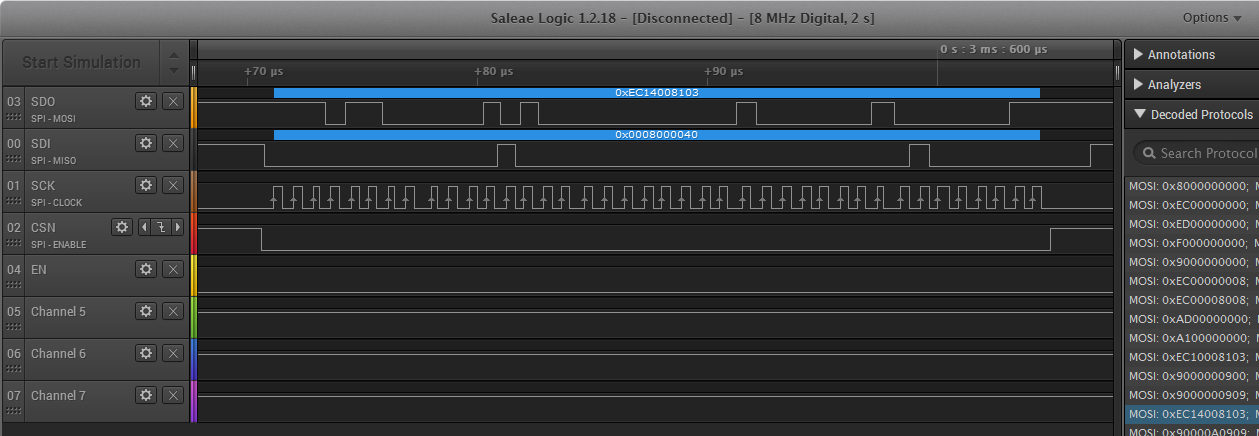
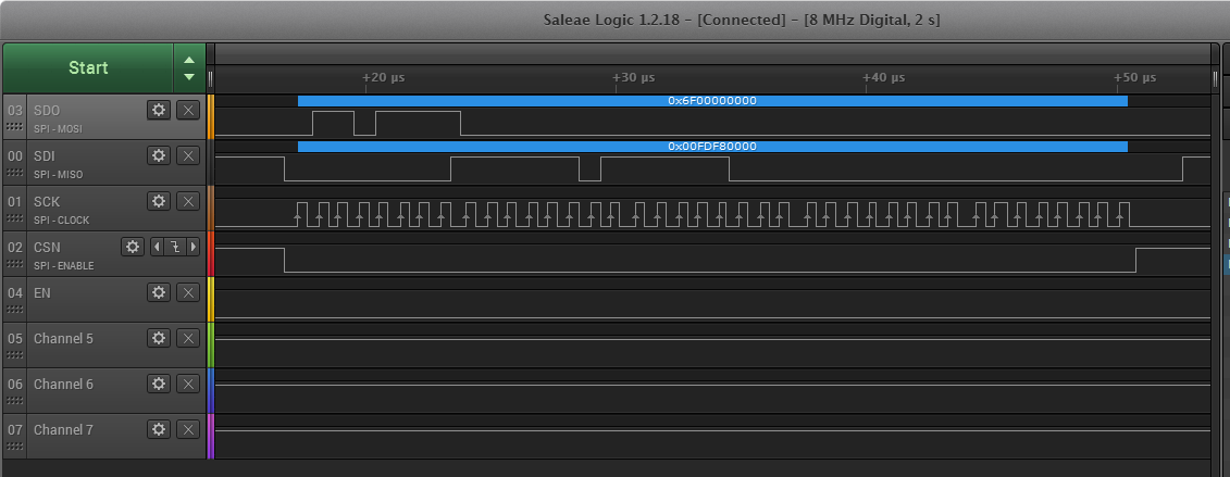
In the other posts i forgot to mention, that i have to use software spi. The Board is a Bigtreetech SKR 1.3. Its a smoothieboard like board. Marlin sends the bits with 80khz and klipper sends the data with 0.9Mhz - 1.2Mhz. Both are using Software spi. See here a register example:
Marlin
Klipper
The bits are the same. Clock seems a little wiggle for klipper. So i tried to reduce the spi_speed and realized that the speedsetting got ignored for software spi(at least for my borad). Is the ignoring of that speedsetting an ecxpected beahvior? If i send the same bits as Marlin does it "works" in 2 of 10 trys. This could be the explaination, why my register reads are courrpted. See here for example the Regster dump for DRV_STATUS:
What klipper gets decoded:
DRV_STATUS: fdf80000 SG_RESULT=0 s2vsa=0 s2vsb=0 stealth=0 fsactive=0 CSACTUAL=248 stallGuard=1 ot=0 otpw=1(OvertempWarning!) s2ga=1(ShortToGND_A!) s2gb=1(ShortToGND_B!) ola=1(OpenLoad_A!) olb=1(OpenLoad_B!) stst=1
What the logic analyzer scoped for that one:
The scoped data, for the init sequence, showed that marlin is sending the whole register, everytime a single field changes. I decoded this sent data here:
GCONF: 00000000 recalibrate=0 faststandstill=0 en_pwm_mode=0 multistep_filt=0 shaft=0 diag0_error=0 diag0_otpw=0 diag0_stall=0 diag1_stall=0 diag1_index=0 diag1_onstate=0 diag1_steps_skipped=0 diag0_int_pushpull=0 diag1_poscomp_pushpull=0 small_hysteresis=0 stop_enable=0 direct_mode=0 test_mode=0
CHOPCONF: 00000000 toff=0 hstrt=0 hend=0 fd3=0 disfdcc=0 chm=0 tbl=0 vhighfs=0 vhighchm=0 tpfd=0 mres=0 intpol=0 dedge=0 diss2g=0 diss2vs=0
COOLCONF: 00000000 semin=0 seup=0 semax=0 sedn=0 seimin=0 sgt=0 sfilt=0
PWMCONF: 00000000 PWM_OFS=0 PWM_GRAD=0 pwm_freq=0 pwm_autoscale=0 pwm_autograd=0 freewheel=0 PWM_REG=0 PWM_LIM=0
IHOLD_IRUN: 00000000 IHOLD=0 IRUN=0 IHOLDDELAY=0
CHOPCONF: 00000008 toff=8 hstrt=0 hend=0 fd3=0 disfdcc=0 chm=0 tbl=0 vhighfs=0 vhighchm=0 tpfd=0 mres=0 intpol=0 dedge=0 diss2g=0 diss2vs=0
CHOPCONF: 00008008 toff=8 hstrt=0 hend=0 fd3=0 disfdcc=0 chm=0 tbl=1 vhighfs=0 vhighchm=0 tpfd=0 mres=0 intpol=0 dedge=0 diss2g=0 diss2vs=0
XTARGET: 00000000
XACTUAL: 00000000
CHOPCONF: 00008103 toff=3 hstrt=0 hend=2 fd3=0 disfdcc=0 chm=0 tbl=1 vhighfs=0 vhighchm=0 tpfd=0 mres=0 intpol=0 dedge=0 diss2g=0 diss2vs=0
IHOLD_IRUN: 00000900 IHOLD=0 IRUN=9 IHOLDDELAY=0
IHOLD_IRUN: 00000909 IHOLD=9 IRUN=9 IHOLDDELAY=0
CHOPCONF: 00008103 toff=3 hstrt=0 hend=2 fd3=0 disfdcc=0 chm=0 tbl=1 vhighfs=0 vhighchm=0 tpfd=0 mres=0 intpol=0 dedge=0 diss2g=0 diss2vs=0
IHOLD_IRUN: 000a0909 IHOLD=9 IRUN=9 IHOLDDELAY=10
TPOWERDOWN: 00000080 TPOWERDOWN=128
GCONF: 00000004 recalibrate=0 faststandstill=0 en_pwm_mode=1 multistep_filt=0 shaft=0 diag0_error=0 diag0_otpw=0 diag0_stall=0 diag1_stall=0 diag1_index=0 diag1_onstate=0 diag1_steps_skipped=0 diag0_int_pushpull=0 diag1_poscomp_pushpull=0 small_hysteresis=0 stop_enable=0 direct_mode=0 test_mode=0
PWMCONF: 000505b4 PWM_OFS=180 PWM_GRAD=5 pwm_freq=1 pwm_autoscale=1 pwm_autograd=0 freewheel=0 PWM_REG=0 PWM_LIM=0
GSTAT: 00000000 reset=0 drv_err=0 uv_cp=0
GCONF: 00000000 recalibrate=0 faststandstill=0 en_pwm_mode=0 multistep_filt=0 shaft=0 diag0_error=0 diag0_otpw=0 diag0_stall=0 diag1_stall=0 diag1_index=0 diag1_onstate=0 diag1_steps_skipped=0 diag0_int_pushpull=0 diag1_poscomp_pushpull=0 small_hysteresis=0 stop_enable=0 direct_mode=0 test_mode=0
DRV_STATUS: 00000000 SG_RESULT=0 s2vsa=0 s2vsb=0 stealth=0 fsactive=0 CSACTUAL=0 stallGuard=0 ot=0 otpw=0 s2ga=0 s2gb=0 ola=0 olb=0 stst=0
I am not the excpert here. For me it looks like that i have an software_spi issue at this high speeds? The documentation on TMC5160 tells us that the driver can communicate up to 4Mhz spi speed. So maybe the board is the point to fix here? Uart is working perfectly on that board, i tried tmc2208 on all sockets.
The scoped communication is attached here as csv for both, Marlin and Klipper.
-Stephan
hi @Stephan3 - thanks very much for the effort - my tmc5160 just laying in front of me waiting to be used ...
The difficulty with SPI is always (for me) to find the right MODE. TMC states Mode 3 (TMC5160 Page 24) - and you also initialize Klipper with Mode 3
self.spi = bus.MCU_SPI_from_config(config, 3, default_speed=4000000)
But if I compare the Code for software SPI between klipper and teamuatlut than here is a different sequence between them. And having had a very short lock at the timing diagram of the TMC - I think that teamualut has a better fit.
So maybe try a different MODE with klipper to see if you get more stable communication !?!?
Klipper https://github.com/KevinOConnor/klipper/blob/master/src/spi_software.c
if (ss->mode & 0x01) {
// MODE 1 & 3
gpio_out_toggle(ss->sclk);
gpio_out_write(ss->mosi, outbuf & 0x80);
outbuf <<= 1;
gpio_out_toggle(ss->sclk);
inbuf <<= 1;
inbuf |= gpio_in_read(ss->miso);
} else {
teamuatlut https://github.com/teemuatlut/TMCStepper/blob/master/src/source/SW_SPI.cpp
for (uint8_t i=0 ; i<8 ; ++i) {
// Write bit
if ( ulBitOrder == LSBFIRST ) {
!!(ulVal & (1 << i)) ? writeMOSI_H : writeMOSI_L;
} else {
!!(ulVal & (1 << (7 - i))) ? writeMOSI_H : writeMOSI_L;
}
// Start clock pulse
writeSCK_H;
// Read bit
if ( ulBitOrder == LSBFIRST ) {
value |= ( readMISO ? 1 : 0) << i ;
} else {
value |= ( readMISO ? 1 : 0) << (7 - i) ;
}
// Stop clock pulse
writeSCK_L;
}
Hello @KevinOConnor .
Lastnight i peeled a avr board out of my trashpile. It has hardware spi polpulated but no stepperdriver sockets. With the ugliest wiring i ever did i hooked the tmc5160 up to that board, flashed klipper to it and gues what? My code is working allready with hardware spi. So it looks like that the skr needs some love regarding to software spi. I cant do that, Its far beyound my abilities. Maybe a limit the spi speed? make it setable by user? No matter if all registers get writen in 0,0018seconds(1,2mhz) or 0,03seconds(100khz). I think noone will notice even with 5160´s rampmode this is still sufficent.
So just now i pushed a working code to github. https://github.com/Stephan3/klipper-tmc5160/tree/master
I did basic tests such as homing (with manual clicking) and a some travels in stealthchop and spreadcycle. The formula for IHOLD is different for tmc5160(calc_current_config). The Treeshold for spreadcycle is sill wrong. For now all i had tested is very smooth. on my 24v power supply i easily speed that motor to 600mm/s+, in stealthchop btw.
For this C code you shown here i cant tell much beside the fact that its beyond my understanding. But as you´ve said its a better fit so maybe you can adopt this? Does this have a negative effect to others? So if you test this and found the code working too, I can clean that up a little and try to PR it.
-Stephan
@Stephan3
would be nice if you could also upload the printer.cfg for the SKR1.3 and TMC5160. ;)
[tmc5160 stepper_x]
cs_pin: ar35
#spi_software_sclk_pin: P0.4
#spi_software_mosi_pin: P4.28
#spi_software_miso_pin: P0.5
microsteps: 16
run_current: 0.8
hold_current: 0.8
sense_resistor: 0.075
stealthchop_threshold: 100
#spi_speed: 100000
of course. this is for hardware spi and @watterott stepperdrivers
oh - do you use the SKR1.3 and the TMC5160 with hardware SPI now?
Actually you are right, I could keep the SKR1.1 and just replace the TMC2130 with the TMC5160. Just wanted to get rid of all the wires ....
No this is, as writen above a hardware spi on a avr board.
https://github.com/bigtreetech/BIGTREETECH-SKR-V1.3/blob/master/hardware/SKR-V1.3-SCH.pdf
I will play tonight with Hardware spi on skr 1.3. It seems they are populated on EXP2.
so I just replaced the X-axis TMC2130 with TMC5160 on an SKR1.1 and changed printer.cfg. SPI is hardware support (no display).
AND its working. However, even with stealthchop_threshold: 100 the motor is much louder than with the 1230 (just tested with force_move).
Also does your TMC5160.py support stallguard?
Neither marlin nor klipper are generating proper Mode 3 signals in the analyzer captures -- SCLK should be high when CSn drops. Unless the logic analyzer is adding an inversion and not displaying the physical signal? There might be a half cycle offset at the receiving end as a result.
The klipper code should be manipulating the clock properly if the mode is configured. This snippet initializes the clock polarity before chip select:
void spi_software_prepare(struct spi_software *ss) { gpio_out_write(ss->sclk, ss->mode < 2 ? 0 : 1); }
I would guess that the software spi is not receiving the mode configuration.
self.spi = bus.MCU_SPI_from_config(config, 3, default_speed=4000000)
This seems like hardware rather than software spi config.
@mattthebaker a warm welcome to the party ;) Take a closer look to bus.py This block tells what to use sw or hw spi https://github.com/KevinOConnor/klipper/blob/f444177bb4794500a6f36d1e12adb8721fc8af35/klippy/extras/bus.py#L116 If a user configs the sw pins it switches so sw spi. I agree to that clock thing you mentioned. Maybe my analyzer software is causing this. I cant tell.
@sniperlucian no stallguard yet(not tested/tried) we are very early here....
Hmm, yeah it seems it should take the config.
Re: analyzer, unless it was told to expect mode 3 it should probably show the physical signal. I studied it a bit closer, if it is displaying they physical signal, then its SPI mode 0, if the clock is displayed inverted, its mode 2.
Still seems to me that the mode config is getting lost somewhere, the mcu code should be able to generate proper mode 3.
Okay, well uh.. it looks like maybe the software spi C code forgets to hold onto the mode config option.
https://github.com/mattthebaker/klipper/tree/soft_spi_mode_fix
I'm not near a printer/pi so I can't compile nor test. That line may need a type cast. Without it, the soft spi c code is definitely ignoring the mode input.
@mattthebaker i had a closer look again, too. the cspin is 1 clock ahead of transfer start. this looks okay to me. So the slave listens. The message starting with clock one is valid and 40 clocks and bits long. So looks okay to me?
EDIT i try that, have the hw here on table, maybe you can look into the "rate" thing also?
The software spi doesn't do anything with rate, it just attempts to generate the signal as fast as it can. Normally that's okay since software is already slow -- though now with the LPC being 100mhz, maybe it could exceed some slave chip ratings. 1Mhz is normally not too difficult for a SPI IC to meet.
It would add a lot of complexity to try to allow settable clock rates (esp. given the support of multiple chips). Best that would be feasible is to slow it down slightly -- though making that run time configurable would reduce the max speed. Unless some devices are really confirmed to not tolerate the speed its best as is.
The AVR running so slow may somehow allow the chip to work properly even with the incorrect mode (though probably with bad timing margins). They should work at full speed no problem in the correct mode though (barring noise or other signal integrity issues).
@mattthebaker
the necessary time delays are in ns (datasheet) - however the MISO has some delay to answer - might depend on mode.
@Stephan3
I got stallguard working (SKR1.1 Hardware SPI and dont forget to bridge CLK). Just included from TMC2130:
sgt = config.getint('driver_SGT',0,minval=-64,maxval=63) & 0x7f
self.fields.set_field("sgt",sgt)
still hoped to get them quiter, and stallguard still quite rough (0 to soft, 1 very hard.) The 2130 have much softer. might be configuration though.
@mattthebaker a warm welcome to the party ;) Take a closer look to bus.py This block tells what to use sw or hw spi
@Stephan3 With mode we dont mean software or hardware SPI. SPI itself has 4 different modes, depending when the data is sampled relative to clock state (flank up, flank down, high, low).
So I agree with @mattthebaker that maybe the mode is not correctly configured when it switches to software mode, cause the clock isnt either.
just reading datasheet of tmc5160 about the stallguard. this is a beast. its possible to read out the mechanical load during homing, so it should be easily possible to integrate an autotune stallguard feature ;)
@mattthebaker i build the firmware with your change. and did a init with modes 0-3, see the file attached. It looks like the the mode is getn honored now. Still no luck on skr 1.3 with spi communication. The data i scoped with analyser looks valid to me as i ecxpect it to be. just had to switch the interpretation in analyser during the modes. I ordered a ramps from amazon for tomorrow. I think we should focus on tmc5160 here, not skr. matt.xlsx
@sniperlucian we dont have all default settings perfectly match. So maybe this is the reason its louder. No matter what stallguard is a thing we can take care of once the core functionality is there.
@Stephan3 interesting, and now the waveforms look correct. Mode 3 is definitely what you want for the tmc5160. The above fix affects software_spi on every mcu.
I'll try not to derail too much, and feel free to rope me in wherever you look closer at SKR. I don't have 5160s so I can't contribute much beyond the signaling/interface.
Beyond just the SPI mode, I did identify the next issue with SKR/Watterott5160. SKR shorted RST and SLP of the stepstick socket -- Watterott5160 put CLK on the SLP pin. This is most likely an issue for the 5160.
Yes, this pin needs to be removed and a bridge closed to ground. Also see here:
https://github.com/MarlinFirmware/Marlin/issues/13607 https://github.com/MarlinFirmware/Marlin/issues/13544
@Stephan3 wasn't meant as offense - opposite I am sure you make a lot of people happy with this. Just printed with 300% speed in stealth without loosing a single step ;) - I just needed to print a gear for my son's RC car - so needed that stallguard urgently.
@mattthebaker your is very welcome! Gz for the find in softspi! Afaik you are arround on the voron discord. Maybe, beside this here, we can get in touch there and take a closer look to that skr thing.
@sniperlucian Did i got it right that i have to disconnect CLK from the board? Or am i able to solder em on the bottom of the board. Sorry for my laziness, this is a monsterthread there and a bit to marlin specific. But one point is still confusing me. Why did it work for me with marlin without the grounding?
The Noise thing: You might try to play with the following values in the defaults:
set_config_field(config, "PWM_OFS", 128) # Marlin 180 # tridoku page 54
set_config_field(config, "PWM_GRAD", 4) # Marlin 5 # 54
set_config_field(config, "pwm_freq", 1) # Marlin 1 # 53
set_config_field(config, "pwm_autoscale", 1)# Marlin 1 # 53
set_config_field(config, "pwm_autograd", 1) # Marlin 1 # 53
set_config_field(config, "freewheel", 0) # Marlin 0 # 53
set_config_field(config, "PWM_REG", 0) # Marlin 0 # 53
set_config_field(config, "PWM_LIM", 0) # Marlin 0 # 53
If one has ideas for making the stealthchop quiter than it currently is, Just give us input here. So if theese points are done this will go to a PR.
For the threshold, which is switching spreadcycle and stealthchop. this needs a fix. The math isn´t right there. I will do that.
@Stephan3 it was working for me first too, than not. SKR1.3 (1.1) connects CLK with the SDO pin. Datasheet from TCM5160 states (page 118) that is automatically switches back to internal clock if it missing 32 clock cycles from external clock. Don't know how reliable that works though ....
After I removed the Pin from the speedstep and connected it to ground(over side of speedstep) they running perfect. just scroll at the second link I send from marlin forum - here is a nice pic of it.
I just want to give an update here. On my working table i do have smooth and quiet running steppers with tmc5160. The next days i will do some code cleaning and some logging fixups. The Coolstep feature is added allready and needs testing.
Hey, thanks for pointing out the SW SPI bug. I've taken a look at the code in TMCStepper and it should follow Mode3 specs better in the next update. I just need to actually test everything first but I don't have all the necessary hardware with me. I also updated LPC SW SPI to around 2.3 - 2.7MHz. We'll see how it works out.
@Stephan3 I tried getting Coolstep implemented as a feature into Marlin and setting it up is quite easy. The hard part is trying to tune it right and also trying to make it easily usable and understandable for the end user. For now I've moved on from the idea.
@sniperlucian You can actually use the stallGuard readout for normal homing as well. This will mean that the user doesn't have to solder in the diag wire to an endstop. I've been using this method of homing since the beginning of the year and it's working quite reliably. I do suggest working in a faster read method. So instead of sending two commands to the driver; first telling the register you want to read and then pushing a dummy to shift the bits out, you rather keep sending the same read commands. This should make it a bit faster to react to the read values.
Another thing if you want to try out is setting an alternative acceleration and jerk profile for the duration of the stallGuard homing. The stallGuard feature works best when there are no sudden changes in movement and you want the movement to be as smooth as possible. I wrote a feature in Marlin that when homing disables jerk and sets acceleration to just 100. It also introduces a guard period to the start of the homing procedure to filter out false positives. Doing something like this can benefit stallGuard homing with both a hardware wire and reading the value through SPI.
I don't want to write too much about Klipper setting up the driver since I don't know the code. At all.
But if you want to compare to Marlin, you can also try using the M122 V [XYZE]
to get the verbose output. This will give you the raw hex patterns of most of the registers.
And yes, just to confirm and reiterate, both Watterott and Trinamic suggest grounding the CLK pin, despite the fall back option. I've pointed this out and hopefully it'll be fixed in the version of the PCB.
@teemuatlut thanks for the information. So i will choose more secure defaults for coolstep. So if youre in charge for the Marlin part also i want to give you that friendly note, that your comments here are maybe misleading.
First thing is that theese default values are not matching the data i had scoped: https://github.com/MarlinFirmware/Marlin/blob/23ec6504103a99a0d769346e2a503a1d1764cf7b/Marlin/src/module/stepper_indirection.cpp#L828
Second is that you might be targeting a diffent result here: https://github.com/MarlinFirmware/Marlin/blob/23ec6504103a99a0d769346e2a503a1d1764cf7b/Marlin/src/module/stepper_indirection.cpp#L853
# marlin: [855] pwmconf.pwm_freq = 0b01; // f_pwm = 2/683 f_clk
# Marlin sets : 0b01 = 10 1 1 00 00 0001 which is:
# pwm_freq = bin 10 - dez 2 - %10: fPWM=2/512 fCLK # marlin comment missleading? # tridoku page 53
# pwm_autoscale = bin 1 - dez 1 - # tridoku page 53
# pwm_autograd = bin 1 - dez 1 - # 53
# freeweel = bin 00 - dez 0 - # 53
# reserved = bin 00 - dez 0 - # 53
# PWM_REG = bin 0001 - dez 1 - # 53
Maybe one did this cause a tmc5160 struct is missing theese days. really no offending, just a friendly hint to team marlin.
-Stephan
@Stephan3
can you send me (or push) your current status ? I would love to try it out.
@teemuatlut I would love that, all those cables drive me crazy ;). For CoreXY however you would need to read them very fast in parallel. Its really a pity that the SKR1.3 only supports soft SPI, which adds a lot of CPU load. Since klipper communication to the µC is message based, I dont know how much delay this would add to the feedback loop, but definitely much more than the DIAG pin. At this point it would make totally sense to implement the stallguard auto tune mentioned in the datasheet.
I think to remember that klippy generates just single steps for homing, so jerk etc. would be disabled anyway.
The other features, coolstep, dc step - sounds very interesting, just dont know how much fine tuning they need for an particular printer. If one stepper always running late, might ruining the print.
I'd rather have someone point out a mistake than stay silent about it. That way the end result can be improved.
I didn't scope the transmissions but I took a look at the shadow registers. (M122 VX
with a few mods)
CHOPCONF = 0x14:00:81:03
toff = 3
hstrt = 0 => hysteresis start = 1
hend = 0b10=2 => hysteresis end = -1
This seems to match with #define CHOPPER_DEFAULT_12V { 3, -1, 1 }
The comment sure is wrong because of a rebase mishap that I haven't fixed yet. There's also no ADAPTIVE_CURRENT
in Marlin even if you see that bit of code right there. The TMC5160 init function should look very close the same as TMC2130.
PWMCONF = 0x00:05:05:B4
Bit 17 = 0
Bit 16 = 1
This would correspond with 0b01 = 2/683
So to me it seems like the bitfields are working alright so either the SPI communication is wrong or maybe there was something in interpreting the scoped data.
Either way, if this is an issue with either Marlin or the library, it might be better to discuss it there rather than on a Klipper ticket. But I'll try to answer any questions here if I can =)
was following this thread, just thought I might add another data point.
SKR V1.3 with TMC5160's + klipper master here. Was on Marlin before and the drivers seemed to work fine. Trying Klipper out with @Stephan3 WIP tmc5160.py. I confirm that I had to solder CLK to GND to make things work properly in Klipper, though they seemed to work just fine in Marlin without. Before I soldered the jumpers, the y stepper wouln't budge and the x and z steppers wouldn't go into stealthchop. Everything seems ok now.
regarding soft vs hard SPI, is it expected to become a bottleneck for Klipper? really liking the absense of a wire mess :)
Cleanup is done here and pushed to my github. The current code worked really well on my voron2 for 18hours. Also i overhauled the Math for current setting to match the datasheet.
I am adding coolstep now and test it the next 12h on my printer. Pull request is very close.
@dralves that is an interesting data point that it works in marlin without grounding clk.
My guess is that the SPI frequency is so low in marlin, that the TMC switches over to external and then fails back to internal clock on some or all SDO edges. Datasheet says the watchdog is looking for 32 missing clocks, which at 12Mhz is 2.5us. Marlin SPI clock period is about 10us which gives enough time to failover, whereas klipper is pushing about 1us clocks. Or maybe the switch to external clock requires the two edges for activation to be fast enough and there is no switchover at all with marlin. Either way it is an abuse of the spec and the behavior of the chip probably undefined. If a temporary switchover actually does occur, who knows what affect that has in the chopper or other subsystems.
Don't confuse system clock CLK with SPI clock SCK.
SDO is connected to TMC CLK, SCK is not involved beyond setting the period at which SDO can toggle.
My guess is that the SPI frequency is so low in marlin, that the TMC switches over to external and then fails back to internal clock on some or all SDO edges.
If that's the case, then one could test Klipper with a hack to slow it down - something like the below (which is totally untested).
-Kevin
--- a/src/spi_software.c
+++ b/src/spi_software.c
@@ -48,6 +48,16 @@ spi_software_prepare(struct spi_software *ss)
gpio_out_write(ss->sclk, ss->mode < 2 ? 0 : 1);
}
+#include "generic/misc.h"
+
+static void
+udelay(uint32_t usecs)
+{
+ uint32_t end = timer_read_time() + timer_from_us(usecs);
+ while (timer_is_before(timer_read_time(), end))
+ ;
+}
+
void
spi_software_transfer(struct spi_software *ss, uint8_t receive_data
, uint8_t len, uint8_t *data)
@@ -73,6 +83,7 @@ spi_software_transfer(struct spi_software *ss, uint8_t receive_data
inbuf |= gpio_in_read(ss->miso);
gpio_out_toggle(ss->sclk);
}
+ udelay(2);
}
if (receive_data)
Feature request: TMC5160 support.