 klipper-gitissuebot
commented
3 years ago
klipper-gitissuebot
commented
3 years ago Hi @AlessandroEmm,
It did not look like there was a Klipper log file attached to this ticket. The log file has been engineered to answer common questions the Klipper developers have about the software and its environment (software version, hardware type, configuration, event timing, and hundreds of other questions).
Unfortunately, too many people have opened tickets without providing the log. That consumes developer time; time that would be better spent enhancing the software. If this ticket references an event that has occurred while running the software then the Klipper log must be attached to this ticket. Otherwise, this ticket will be automatically closed in a few days.
For information on obtaining the Klipper log file see: https://github.com/KevinOConnor/klipper/blob/master/docs/Contact.md
The log can still be attached to this ticket - just add a comment and attach the log to that comment.
Best regards, ~ Your friendly GitIssueBot
PS: I'm just an automated script, not a human being.
 AlessandroEmm
 KevinOConnor
 github-actions[bot]
 Lefuneste83
 t3chguy
 M1dn1ghtN1nj4
 SemenHHH
 amorim1005
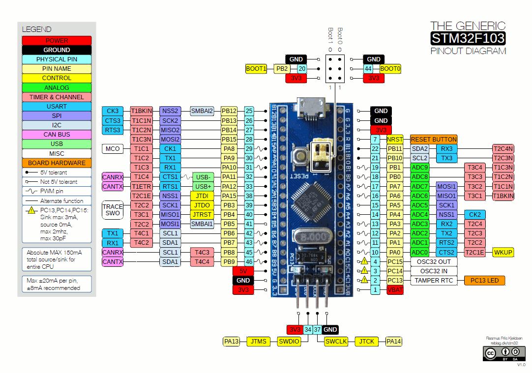
Hey there
So I tried getting this to work but I always end up in a i2c comm error, which makes sense since default pins are set to the values for 1.2 board it seems: https://github.com/KevinOConnor/klipper/blob/5773654a00443dc5e1b6e3ce195c48a5688c3aac/src/stm32/i2c.c#L21 and https://github.com/KevinOConnor/klipper/blob/5773654a00443dc5e1b6e3ce195c48a5688c3aac/src/stm32/i2c.c#L25 ->
Whereas on the 2.0 it's PA15/ and PB15 https://user-images.githubusercontent.com/31118252/85957631-ed71a800-b95c-11ea-9776-2bb7f3304a1d.png
So how would I change this via config (given its the actual problem)? I tried changing the source and recompiling but still would run into the same problem ({ I2C1, GPIO('A', 15), GPIO('B', 15) }, . Display-config is bone stock.
Thanks a lot Alessandro