Closed BambOoxX closed 1 year ago
I think the way to go about this is to create a separate Scene for the indicator and update its view matrix based on the parent plot.
With an LScene
(using some 3d camera) this involves reading out eyeposition, lookat and upvector, moving lookat to 0 and adjusting eyeposition to a comfortable zoom level:
# Your plot
fig = Figure()
lscene = LScene(fig[1,1])
p = scatter!(rand(Point3f, 10))
display(fig)
scene = Scene(
fig.scene, px_area = Rect2f(20, 20, 100, 100),
# backgroundcolor = RGBAf(1,1,0), clear = true # to see scene region
);
linesegments!(scene,
Point3f[(0,0,0), (1,0,0), (0,0,0), (0,1,0), (0,0,0), (0,0,1)],
color = [:red, :red, :green, :green, :blue, :blue],
linewidth = 10
)
cam = cameracontrols(lscene.scene)
scene.camera.projection[] = Makie.perspectiveprojection(45f0, 1f0, 0.01f0, 100f0)
onany(cam.lookat, cam.eyeposition, cam.upvector) do lookat, eyepos, up
viewdir = 4f0 * normalize(eyepos - lookat)
scene.camera.view[] = Makie.lookat(viewdir, Vec3f(0), up)
return
end
With an Axis3 you need to read out the relevant angles and calculate eyeposition from that:
fig = Figure()
ax = Axis3(fig[1,1])
p = scatter!(ax, rand(Point3f, 10))
display(fig)
scene = Scene(
fig.scene, px_area = Rect2f(20, 20, 100, 100),
backgroundcolor = RGBAf(1,1,0), clear = true # to see scene region
);
linesegments!(scene,
Point3f[(0,0,0), (1,0,0), (0,0,0), (0,1,0), (0,0,0), (0,0,1)],
color = [:red, :red, :green, :green, :blue, :blue],
linewidth = 10
)
scene.camera.projection[] = Makie.perspectiveprojection(45f0, 1f0, 0.01f0, 100f0)
onany(ax.elevation, ax.azimuth) do theta, phi
viewdir = 4f0 * Vec3f(cos(theta) * cos(phi), cos(theta) * sin(phi), sin(theta))
scene.camera.view[] = Makie.lookat(viewdir, Vec3f(0), Vec3f(0,0,1))
return
end
Thanks @ffreyer ! I will test that ASAP. Quick question, give that you must add a scene with this solution, it's not possible to make a recipe out of it, right? Or is it?
It's possible but more cumbersome. Within an LScene
you can grab parent_scene(plot).camera_controls
and you should be able to pass projection
and view
as plot attributes within the recipe. Though I'm not sure if this works across all backends and I consider it more of a hack. Alternatively you can apply the matrix transforms manually and use space = :clip
.
Dealing with an Axis3
from a recipe is harder. I don't think there is a clean way to trace back to it so if you wanted to be general you'd need to extract a rotation matrix from parent_scene(plot).camera.view
.
Why not just write a function?
I guess I just thought using a recipe would make it more versatile. Also, I'd like to remain as close as possible to MakieCore
but I guess its not possible to avoid Makie
on this.
So, I've been able to get this through a bit of fiddling (basically replacing scene
by scene.scene
) since I'm using an LScene
for the sub-scene (woahhh a lot of scenes in this sentence).
Now it's not directly related, but how is the 3D text rotation handled, I couldn't find an example on that... I tried to see how an LScene
is initialized but I did not understand how the axis labels were handled.
I think you can specify a Vector of Vec3f as a rotation (per string/position). If not a Vector of (Makie) Quaternionf's should work (Makie.qrotation(axis, angle)
for example)
I put something interactive together. You can click on the mesh to switch to different views.
using GLMakie
using GeometryBasics, Statistics, LinearAlgebra
function gen_mesh()
o = 1 / (1 + sqrt(2))
ps = Point3f[
(-o, -o, -1), (-o, o, -1), (o, o, -1), (o, -o, -1),
(-1, o, -o), (-o, 1, -o), (o, 1, -o), (1, o, -o),
(1, -o, -o), (o, -1, -o), (-o, -1, -o), (-1, -o, -o),
(-1, o, o), (-o, 1, o), (o, 1, o), (1, o, o),
(1, -o, o), (o, -1, o), (-o, -1, o), (-1, -o, o),
(-o, -o, 1), (-o, o, 1), (o, o, 1), (o, -o, 1),
]
QF = QuadFace
TF = TriangleFace
faces = [
# bottom quad
QF(1, 2, 3, 4),
# bottom triangles
TF(2, 5, 6), TF(3, 7, 8), TF(4, 9, 10), TF(1, 11, 12),
# bottom diag quads
QF(3, 2, 6, 7), QF(4, 3, 8, 9), QF(1, 4, 10, 11), QF(2, 1, 12, 5),
# quad ring
QF(13, 14, 6, 5), QF(14, 15, 7, 6), QF(15, 16, 8, 7), QF(16, 17, 9, 8),
QF(17, 18, 10, 9), QF(18, 19, 11, 10), QF(19, 20, 12, 11), QF(20, 13, 5, 12),
# top diag quads
QF(22, 23, 15, 14), QF(21, 22, 13, 20), QF(24, 21, 19, 18), QF(23, 24, 17, 16),
# top triangles
TF(21, 20, 19), TF(24, 18, 17), TF(23, 16, 15), TF(22, 14, 13),
# top
QF(21, 24, 23, 22)
]
remapped_ps = Point3f[]
remapped_fs = AbstractFace[]
remapped_cs = RGBf[]
remapped_index = Int[]
for (idx, f) in enumerate(faces)
i = length(remapped_ps)
append!(remapped_ps, ps[f])
push!(remapped_fs, length(f) == 3 ? TF(i+1, i+2, i+3) : QF(i+1, i+2, i+3, i+4))
c = RGBf(abs.(mean(ps[f]))...)
append!(remapped_cs, (c for _ in f))
append!(remapped_index, [idx for _ in f])
end
_faces = decompose(GLTriangleFace, remapped_fs)
return GeometryBasics.Mesh(
meta(
remapped_ps;
normals = normals(remapped_ps, _faces),
color = remapped_cs,
index = remapped_index
),
_faces
)
end
function connect_camera!(ax::Axis3, scene::Scene)
scene.camera.projection[] = Makie.perspectiveprojection(45f0, 1f0, 0.01f0, 100f0)
onany(ax.elevation, ax.azimuth) do theta, phi
viewdir = 3f0 * Vec3f(cos(theta) * cos(phi), cos(theta) * sin(phi), sin(theta))
scene.lights[1].position[] = viewdir
scene.camera.view[] = Makie.lookat(viewdir, Vec3f(0), Vec3f(0,0,1))
return
end
notify(ax.elevation)
return
end
function connect_camera!(lscene::LScene, scene::Scene)
cam = cameracontrols(lscene.scene)
scene.camera.projection[] = Makie.perspectiveprojection(45f0, 1f0, 0.01f0, 100f0)
onany(cam.lookat, cam.eyeposition, cam.upvector) do lookat, eyepos, up
viewdir = 3f0 * normalize(eyepos - lookat)
scene.lights[1].position[] = viewdir
scene.camera.view[] = Makie.lookat(viewdir, Vec3(0.0), up)
return
end
notify(cam.lookat)
return
end
function update_camera!(ax::Axis3, phi, theta)
ax.azimuth[] = phi
ax.elevation[] = theta
return
end
function update_camera!(lscene::LScene, phi, theta)
cam = cameracontrols(lscene.scene)
dir = Vec3f(cos(theta) * cos(phi), cos(theta) * sin(phi), sin(theta))
cam.eyeposition[] = cam.lookat[] + norm(cam.eyeposition[] - cam.lookat[]) * dir
return
end
function reference_frame(parent, bbox = Rect2f(20, 20, 100, 100))
scene = Scene(
Makie.rootparent(parent.blockscene), px_area = bbox,
backgroundcolor = RGBAf(1,1,1,1), clear = true
)
m = gen_mesh()
mp = mesh!(scene, m, transparency = false)
tp = text!(scene,
1.05 .* Point3f[(-1, 0, 0), (1, 0, 0), (0, -1, 0), (0, 1, 0), (0, 0, -1), (0, 0, 1)],
text = ["-X", "X", "-Y", "Y", "-Z", "Z"],
align = (:center, :center),
rotation = [
Makie.qrotation(Vec3f(1, 0, 0), pi/2) * Makie.qrotation(Vec3f(0, 1, 0), -pi/2),
Makie.qrotation(Vec3f(1, 0, 0), -pi/2) * Makie.qrotation(Vec3f(0, 1, 0), pi/2),
Makie.qrotation(Vec3f(0, 1, 0), 0) * Makie.qrotation(Vec3f(1, 0, 0), -3pi/2),
Makie.qrotation(Vec3f(1, 0, 0), pi/2),
Makie.qrotation(Vec3f(1, 0, 0), pi),
Makie.qrotation(Vec3f(1, 0, 0), 0),
],
markerspace = :data, fontsize = 0.4, color = :white,
strokewidth = 0.1, strokecolor = :black, transparency = false
)
connect_camera!(parent, scene)
on(events(scene).mousebutton, priority = 20) do event
if event.button == Mouse.left && event.action == Mouse.press
p, idx = Makie.pick(scene)
if p === tp.plots[1]
phi, theta = [
(pi, 0), (pi, 0), (0, 0), (-pi/2, 0), (-pi/2, 0),
(pi/2, 0), (0, -pi/2), (0, -pi/2), (0, pi/2)
][idx]
update_camera!(parent, phi, theta)
elseif p === mp
face_idx = m.index[idx]
phi, theta = [
(-pi/2, -pi/2),
(3pi/4, -pi/4), (1pi/4, -pi/4), (7pi/4, -pi/4), (5pi/4, -pi/4),
(pi/2, -pi/4), (0, -pi/4), (-pi/2, -pi/4), (-pi, -pi/4),
(3pi/4, 0), (2pi/4, 0), (pi/4, 0), (0, 0),
(7pi/4, 0), (6pi/4, 0), (5pi/4, 0), (pi, 0),
(pi/2, pi/4), (pi, pi/4), (3pi/2, pi/4), (0, pi/4),
(5pi/4, pi/4), (7pi/4, pi/4), (pi/4, pi/4), (3pi/4, pi/4),
(-pi/2, pi/2)
][face_idx]
update_camera!(parent, phi, theta)
end
end
end
return scene
end
This can be used with either Axis3
or LScene
:
fig = Figure()
ax = Axis3(fig[1,1])
p = scatter!(ax, rand(Point3f, 10))
display(fig)
scene = reference_frame(ax);
fig = Figure()
lscene = LScene(fig[1,1])
p = scatter!(rand(Point3f, 10))
display(fig)
scene = reference_frame(lscene);
This is awesome ! I think I'm gonna slightly alter the style but it's really nice ! Thanks for your help.
Quick note : There is a Vec3
instead of a Vec3f
in the connect_camera!
for LScene
.
Ha nice! I implemented something like this for the predecessor of GLMakie, which was still called GLVisualize: https://vimeo.com/184020541 I don't us it in the video, but it was working pretty similar to 3Ds max back then ;)
You did a lot already (and even more so) but here are some questions about this solution
o = 1 / (1 + 0.15)
but it makes the cube overflow the bounding box ? zoom!
doesn't seem to work in this case...If you want to make the visualization larger or smaller you can change the 3f0
in connect_camera!
. The o
in the mesh generation comes from the constraint that each square should have the same side length. (If you consider an octagon in a -1 .. 1 square, o is the offeset from 0 that the corners have. I.e. (o, 1), (-1, -o), etc.)
For an LScene you can probably just set cam.upvector
. Axis3 is keeping the up direction steady on its own.
You mean modifying the interaction as
up0 = Vec3f(0,0,1) #0, 0, 1 for z direction up vector
onany(cam.lookat, cam.eyeposition, cam.upvector) do lookat, eyepos, up
viewdir = 3f0 * normalize(eyepos - lookat)
scene.lights[1].position[] = viewdir
scene.camera.view[] = Makie.lookat(viewdir, Vec3(0.0), up0) #? So that the sun scene follows the z direction
cam.upvector[] =up0#? So that the main scene follows the z direction
return
end
I have tried something close to that but got a stackoverflow ^^
I was thinking here
function update_camera!(lscene::LScene, phi, theta)
cam = cameracontrols(lscene.scene)
dir = Vec3f(cos(theta) * cos(phi), cos(theta) * sin(phi), sin(theta))
cam.eyeposition[] = cam.lookat[] + norm(cam.eyeposition[] - cam.lookat[]) * dir
return
end
That would trigger only when you click on a face.
Just for information, I wanted to put the "cube" in the top right corner so I used the px_area
of the rootparent
and added an event with the following signature
widths=Vec2(200, 200)
root = Makie.rootparent(parent.blockscene)
on(events(root).window_area, priority=20) do event
scene.scene.px_area = Rect2i(event.widths - widths, widths)
end
so that when the window is resized, the cube remains at the same position in the top right corner.
Also while trying to lock the vertical axis I had to detect when theta
would be close to the vertical otherwise when clicking on the +/- Z faces I'd get a blank screen.
function update_camera!(lscene::LScene, phi, theta)
cam = cameracontrols(lscene.scene)
dir = Vec3f(cos(theta) * cos(phi), cos(theta) * sin(phi), sin(theta))
cam.eyeposition[] = cam.lookat[] + norm(cam.eyeposition[] - cam.lookat[]) * dir
if theta≈ π / 2 || theta≈ -π / 2
cam.upvector[] = Vec3f(1, 0, 0)
else
cam.upvector[] = Vec3f(0, 0, 1)
end
return
end
There are still some glitches though, as I get some BoundsError
sometimes while updating the camera. Not sure why yet...
@ffreyer Thanks again for all the help ! I will close this now, but maybe this could be added to some documentation or beautiful Makie fort instance. What do you think ?
It is common in 3D CAD software to have a reference frame displayed in the picture
e.g. this in CATIA Solidworks
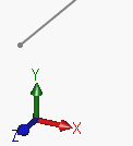
It's fairly obvious that one can reproduce that in GLMakie with arrows, however, it can't figure how to have the arrow origin remain fixed in pixel space. Is there a way to achieve this. I'm guessing something quite equivalent to the
:pixe
oftext
would be nice. The arrow should however rotate according to the:data
space and the camera angles