 sky4fly
commented
5 years ago
sky4fly
commented
5 years ago It may be that the digital driver does not understand the split of the step signal (double, quad multistepping) and because of this there is a bias?
Closed sky4fly closed 4 years ago
sky4fly
commented
5 years ago It may be that the digital driver does not understand the split of the step signal (double, quad multistepping) and because of this there is a bias?
 Bob-the-Kuhn
commented
5 years ago
Bob-the-Kuhn
commented
5 years ago Holy cow!! And I thought I was running some big steppers on my printer! I only expected to see something like this on big CNC machines.
Yes, Marlin can drive this device but it'll take a lot of tuning to get the maximum performance. And chances are maximum performance won't be what you hoped for.
The data sheet says 10uS pulse for reliable operation. Rule of thumb is you need about the same amount of off time as you have on time. Probably best to keep the step rate under 50KHz.
The interface is via optoisolators. You can seriously degrade their speed by over driving them. You may want to experiment with series resistors to see if that helps. You might even be able to get reliable operation at pulse rates above 50K.
I have no idea of your experience level so bear with me if you've been through all this already. I've been on a quest to quiet down my sow's ear by going to higher microstep rates. Here's what I learned about my system:
I have a home built CNC machine with interchangeable heads. As a CNC machine it's OK. It's just too big and heavy to do decent 3D prints in a reasonable time frame. Over the last few years I've watched the printer prices drop and the performance improve so I finally put my money down on a mid-range delta printer.
Bob-the-Kuhn
commented
5 years ago I just realized you mentioned the DRV8825 in your post. I hope you have better experience than I did. My high current drivers had very little performance improvement over the original A4988 drivers. Over the years I tried almost every new driver that came out in that form factor. Most just went into overcurrent and didn't budge the steppers. A couple were able to move the steppers but at slower speeds. I finally tried a couple of off board drivers with mixed results.
sky4fly
commented
5 years ago I tried all the options, everything is useless.
I connected the driver TB6600. It also blends along the X axis of the photo below. Timings are right.

If you are using the drv8825 X axis driver, then there are no shifts !!!
I want to change the board for MKS sbase and pour marlin on it. If there are offsets, then I'll fill in smoothiware, but there is no dual motor implemented there.
Can an incorrect signal be sent to an external driver?
Bob-the-Kuhn
commented
5 years ago You've lost some steps. Has to be jerk, acceleration and/or speed.
Once you find a working combo then vary one thing at a time when finding the limits.
Have you tried using the same settings for the em705 as work on the DRV8825?
Desperation - setup the em705 to mimic the working DRV8835 (same current, same microsteps) and set jerk, accel and speed to a tenth of the ones that work with the DRV8825.
sky4fly
commented
5 years ago Do you know what surprises?
Speeds and accelerations are the same and they are very low.
G-gode in the slicer is also the same. All settings for dravers are the same.
Drv8825 offset is not! The leadshine em705 and tb6600 give offsets. All parameters are the same except for timings !!!
Bob-the-Kuhn
commented
5 years ago What timing is different?
Bob-the-Kuhn
commented
5 years ago Maybe changing how you look at the situation can help. Pretend you're being called in to help a friend setup his new system. What steps would you take to find the optimum settings?
sky4fly
commented
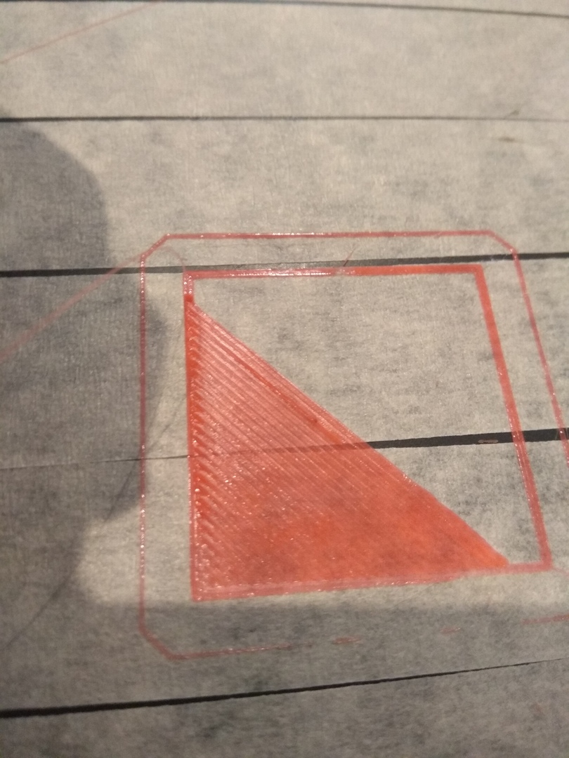
5 years ago I noticed a very interesting thing !!!
If you put microstep 512, then there is practically no displacement. The edges are slightly worse than on drv8825.
Left DRV8825 microstep 16, in the middle of Leadshine em705 microstep 512, on the right Leadshine em705 microstep 16.

The settings in marlin are the same, the timings, the acceleration of the simplicity in the slicer are the same, everything was identical except for the timings.
Microstep 512 is not a solution to the problem!!!
my wiring diagram.

Solution of the problem, what could be wrong ???
sky4fly
commented
5 years ago All my experiments indicate that the #define MINIMUM_STEPPER_DIR_DELAY function does not work.
This follows from the fact that with microstep 32 there are strong displacements, and since 512 there is almost no.
You have the option of checking this parameter. I do not see other problems !!!
Bob-the-Kuhn
commented
5 years ago No changes to anything except 512 in the em705 and it helps a lot.
I don't understand how that would help. Just changing to 512 in the em705 should result in a much smaller cube.
You must be programming the em705 via the RS232 link because 512 is not available via the switches. Can you provide the link to the RS232 instructions?
What are you trying to accomplish by using the em705? Lower noise via higher microstep settings? Higher speed via more power to the stepper?
sky4fly
commented
5 years ago 1) 512 microstep is available via switches.
2) I need microstep 32, 512 was set up as an experiment.
3) The official store Leadshine
4) Today I connected and checked the driver through an oscilloscope. a) Logic control (Step) in fact 2.3 Volts, instead of the declared 3.3 on Arduino DUE. For the driver you need 5 volts. b) The pulse time varied, which means the function #define MINIMUM_STEPPER_PULSE is working. c) It seems to me that there is a bug in marlin. The #define MINIMUM_STEPPER_DIR_DELAY function does not work if the double Z and Y axes are enabled. d) Since there is an auto-calibration, then 6 axes are activated during printing. There is a possibility that because of this, STEPPER_DIR_DELAY is not working correctly. This indicates that the layers are shifting constantly and in the same direction !!!
Do you have the opportunity to check this?
This driver is silent and has excellent features. It is a pity that there is a problem with Marlin.
Bob-the-Kuhn
commented
5 years ago I see the 512 claim but the highest switch setting I see is 25600 which is 128 microsteps.
The DRV8825 has a 32 microstep mode. Does it work for you?
sky4fly
commented
5 years ago Yes, it works, with microstep 32 on drv8825 there are no offsets !!!
sky4fly
commented
5 years ago Found the cause of the displacement of the layers, the dir parameter does not change!
 boelle
commented
5 years ago
boelle
commented
5 years ago @rusnob so this is "fixed"
sky4fly
commented
5 years ago At the moment of changing the dir signal, an extra step impulse occurs. This can be seen even on the basis of your diagrams.
https://github.com/MarlinFirmware/Marlin/issues/13559

This step step is a terminating pulse, i.e. last one.
Suppose if you set 44 pulses per 1 mm axis displacement. Then this extra step will appear on the 44th impulse when the DIR signal changes
How to remove this extra momentum step.
I repeat. In the firmware reprap firmware everything works. In marlin, this pulse is fatal.
thank
boelle
commented
4 years ago @rusnob is this still a problem?
boelle
commented
4 years ago Lack of Activity This issue is being closed due to lack of activity. If you have solved the issue, please let us know how you solved it. If you haven't, please tell us what else you've tried in the meantime, and possibly this issue will be reopened.
 cemi123
commented
4 years ago
cemi123
commented
4 years ago hei. did you solve this problem ?
 github-actions[bot]
commented
4 years ago
github-actions[bot]
commented
4 years ago This issue has been automatically locked since there has not been any recent activity after it was closed. Please open a new issue for related bugs.
Hello all!
External driver leadshine em705 transmits pulses. Is marlin compatible with digital driver? I asked this question in the group facebook
X-axis offset occurs with the leadshine em705 driver. http://www.leadshine.com/UploadFile/Down/EM705d_P.pdf print result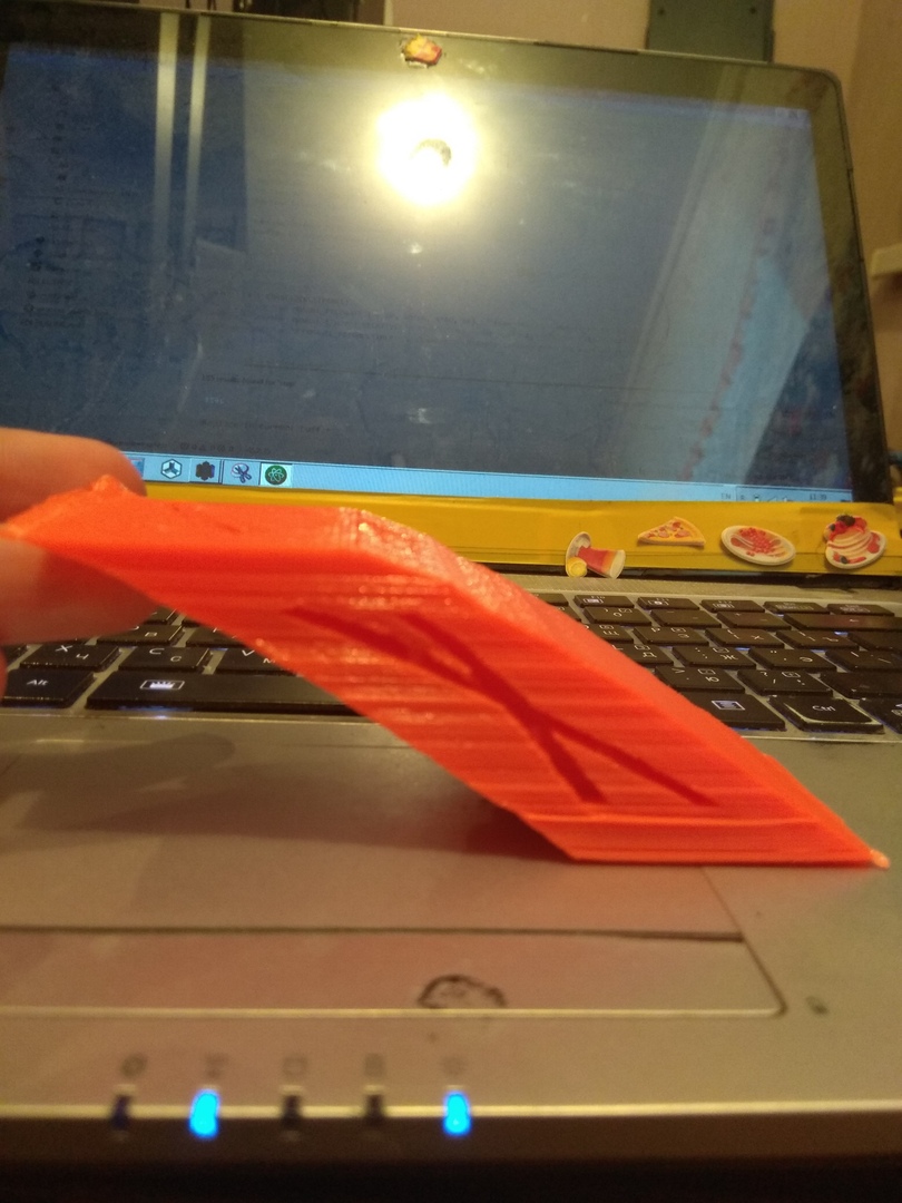
If you use drv8825 offsets are not.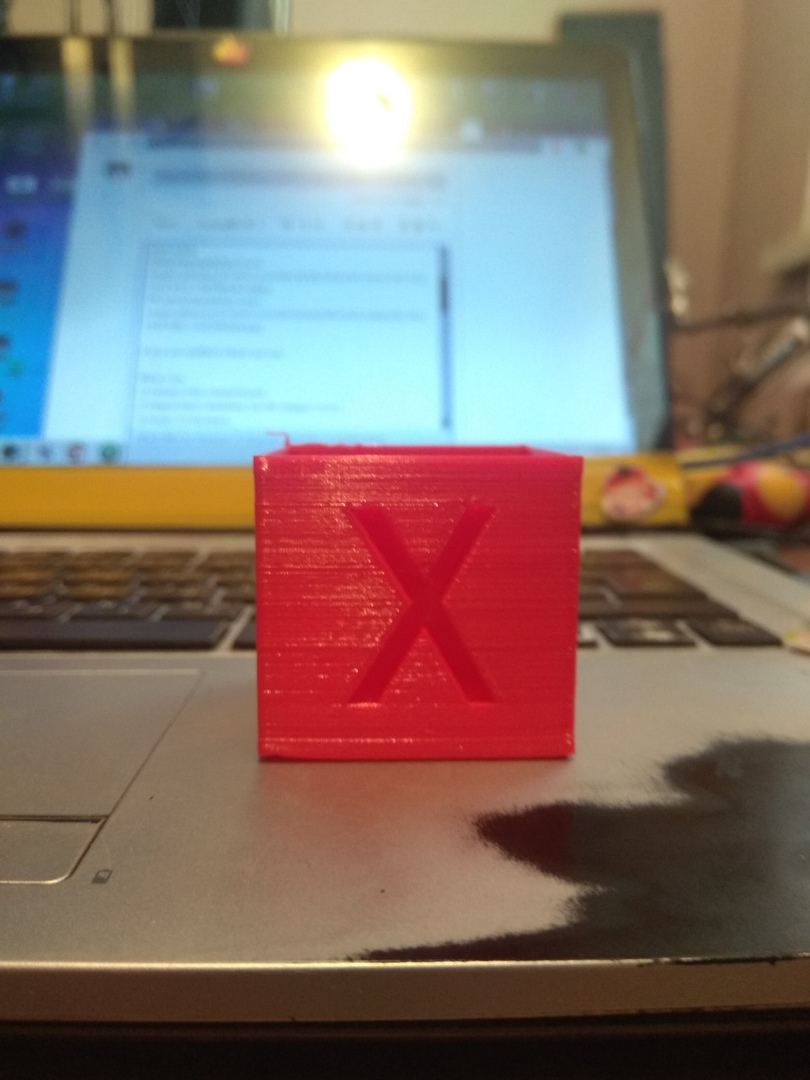
What i use 1) Arduino DUE control board. 2) Digital driver leadshine em705 stepper motor. 3) marlin 2.0 firmware
What I changed to marlin.
1109 screeching. In the configuration_adv.h tab, I uncommented and entered the necessary values for my driver.
define MINIMUM_STEPPER_DIR_DELAY 5000
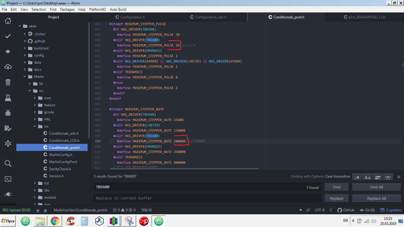
define MINIMUM_STEPPER_PULSE 10
define MAXIMUM_STEPPER_RATE 200000
It did not help.
I thought marlin simply did not see these parameters. For this reason, I indicated in the configuration.h tab a driver for the Tb6600 X axis.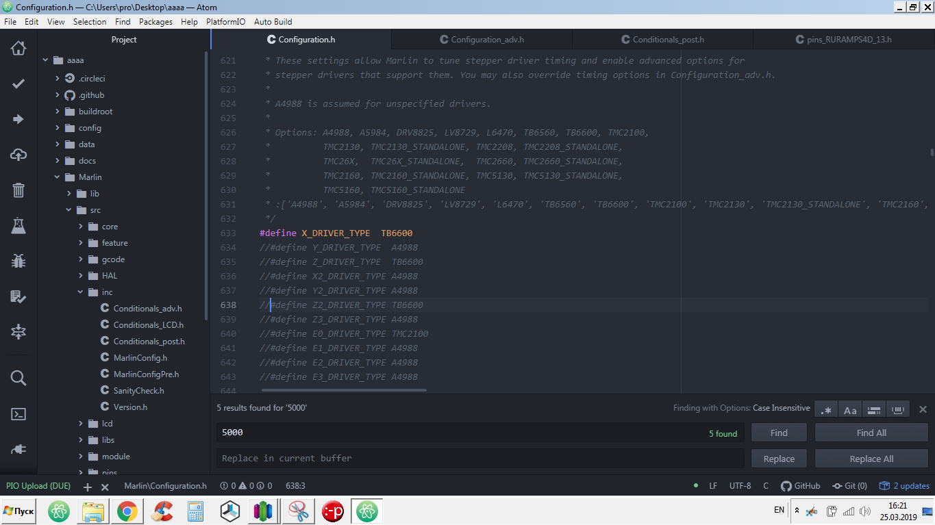
In the \ src \ inc \ Conditionals_post.h tab, tb6600 has its own parameters for the leadshine em705 driver.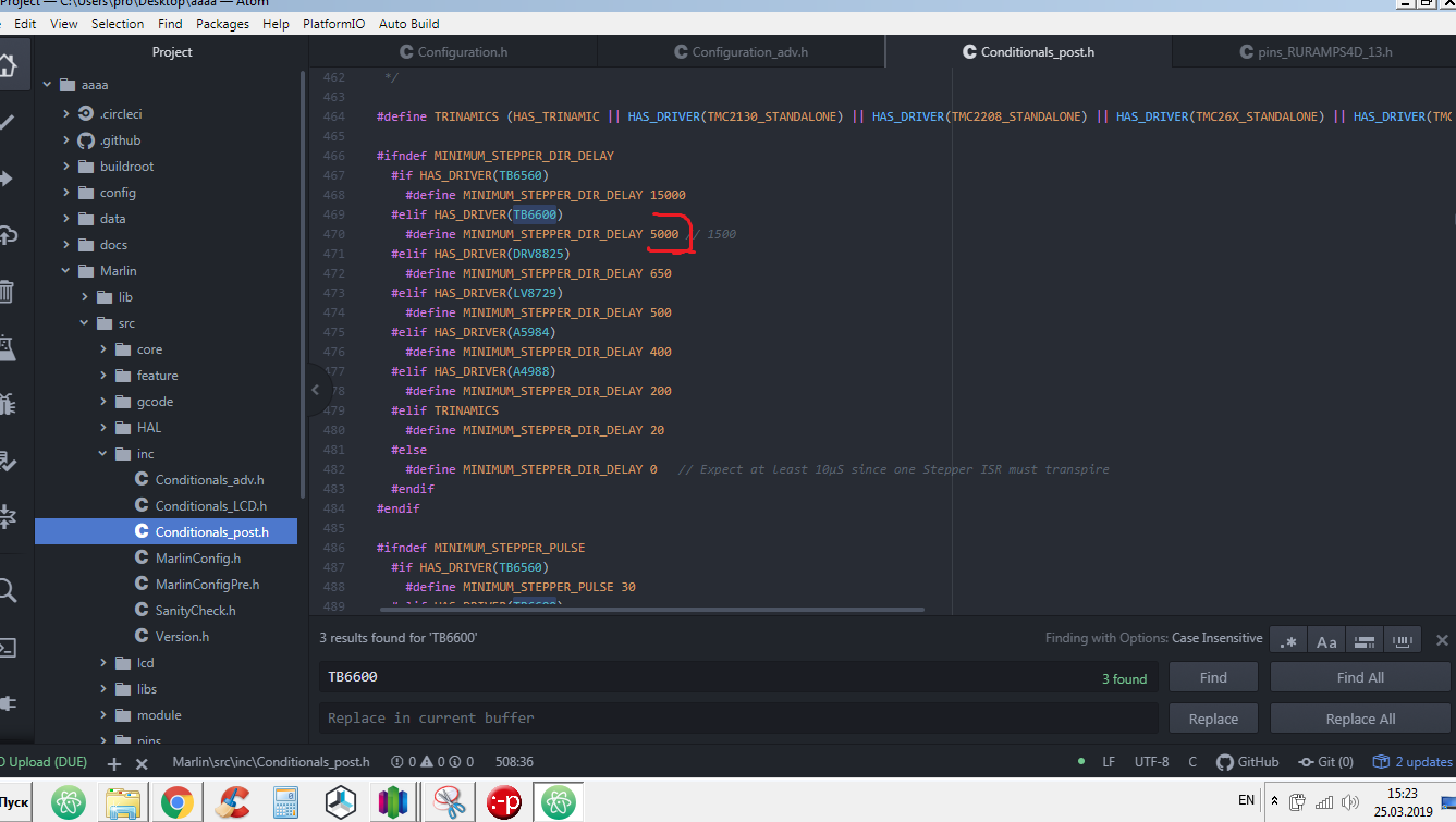
And it did not work. Is marlin compatible with digital drivers? How to properly configure the driver for marlin?
Really looking forward to your comment on this.