Closed zbyrek closed 2 years ago
Ok, I did everything I was certain that would work. Compile completed with no errors but when I attempted to execute M9891 I still receive "echo:Unknown command: "M9891 PA0 F10"".
Attached is a zipped folder of only those files I added or modified including their paths.
Please review and see where I missed something. I'm not a programmer but I'm learning how to modify files and compile them. Still not clear how to read or develop code.
Thanks again. Marlin-For Ender-3 Using Laser.zip
You shouldn't surround that new command block with if statement since you don't define it anywhere else, remove these preprocessor directives.
- #if ENABLED(9891)
{ case 9891:M9891();
break;
}
- #endif
Hi @vojto1980 , Where do you set the frequency value? Sorry for my noob question. I'm now with this stuff. Greetings, Luciano.
Ok, this is a bit frustrating. LOL
So I reviewed @HofaTheRipper "FastPWM.txt" file from is repository and noted that all steps he has listed have been performed. I even went so far as to copy and paste each requirement into appropriate file and their locations.
And to be clear, here is the verbatim list of tasks I followed from Hofa's list.
Set {&gpioa, &timer5, &adc1, 0, 1, 0}, / PA0 / in /Users/%USERPROFILE%/.platformio/packages/framework-arduinoststm32-maple/STM32F1/variants/generic_stm32f103r/boards.cpp
Commented #define FAN_SOFT_PWM in Marlin/src/pins/stm32f1/pins_CREALITY_V4.h
Uncommented #define FAST_PWM_FAN in Marlin/Configuration.h
Commented #define FAN_SOFT_PWM in Marlin/Configuration.h (DO NOT comment out #define SOFT_PWM_SCALE 0)
Set #define STEP_TIMER_NUM 4 // for other boards, five is fine. in Marlin/src/HAL/STM32F1/timers.h
gcode.h:
...
gcode.cpp:
...
Add file gcode\M9891.cpp:
void GcodeSuite::M9891() { const uint8_t pport = parser.byteval('P');
const uint16_t dfreq = parser.ushortval('F');
// Set frequency for port
set_pwm_frequency((pin_t)pport, (int)dfreq);
I guess (because i didn't see whole code) you put case outside switch (after switch closing }
)
After doing some reviewing, I now understand what you were referring to. I moved the line "case 9891: M9891(); break;" up to and between
#if ENABLED(MAX7219_GCODE)
case 7219: M7219(); break; // M7219: Set LEDs, columns, and rows
#endif
case 9891: M9891(); break; //Send GCode command to printer to set port and frequency desired (P<portname> F<frequency in Hz>)
default:
parser.unknown_command_warning();
break;
This allowed the complying to complete with no error message.
I also performed via serial connection and received and "ok" message one I hit return on M9891. Is there a process to see the entered command was successful other than an "ok" response?
want to thank @zbyrek for creating this bug and explaining the issue with a provided fix(work-around), what really helped me getting grayscale laser engraving to work on my Ender 3 v2 in addition to @zybrek changes was:
uncommenting '#define LASER_SYNCHRONOUS_M106_M107' suggested by @vojto1980.
cheers guys👍😊
@descipher are those fixes included in bugfix or Marlin firmware ? Have Creality 4.2.2 board and after compiling bugfix and also Marlin HW pin is still dead ,board is new ,everything works fine even that k1 fan but when i connect laser to it just blinks laser and nothing else
@VukIgor #23125 was merged after your compile, please use bugfix-2.0.x which now contains the fix.
@descipher thank you very much :) Hope it won't need any aditional coding becouse i'm noob at this ,have few laser engravers running on marlin and ramps 1.4 for more than year without issue
Bugfix works for my creality 4.2.2 boards ,thank you
Hi there, I want to share my observations with the Ender 3 v2 and 500mW laser. I also had a problem with slow PWM. So I did all the tweaks suggested by @zybrek and @vojto1980. Awesome, it worked! Thank you. Nice and precise engraving with the possibility to control the laser power.
BUT, then I started to burn 15 min program. After ca. 10 mins, something happened and the output from the connector now gives 100% power (24V) all the time. It is no more possible to control this output. I also tried stock firmware, but it still gives 100%.
For me, it looks, something may be burned in the mainboard. For that "fatal" engraving I had used about 5% of laser power and the mainboard fan (which was connected to the same connector) was not running at all, so maybe it got overheated, I do not know. Fortunately, the other features are OK, I can 3D print as before, only the fan still rotates at full speed now.
Take care, Michal
You probably burned transistor, higher frequency switching create bigger losses due to capacitance of transistor which leads to more power dissipated, so it could overheat, only way to check this is to desolder transistor and measure it outside circuit. That disconnected mainboard fun was terrible idea.
some vendors/boards use OD (open drain) mode to drive mosfets, which allow more power on outputs... But to know that, you need a real schematic (or reverse/inspect the pcb to make one).... basically, the output is linked to 5V with a resistor to be able to give more juice to the mosfet... but in result, the pwm/output signal may be reversed... give juice when set to 0
sample: H1/2/3 are STM32 3.3V outputs
gives 100% power (24V) all the time.
Sorry to hear it failed.
Depending on what device you are driving a voltage of 24 may be too high for it. This could easily damage a diode laser pwm control signal input.
But yes regardless of that, there is the high frequency issue that can cause a MOSFET or Transistor to overheat and short out.
I used the official Creality "laser set" that allows 12-24V on input. The laser is still working. Most probably the transistor is dead. My board is v4.2.2.
Since the other functions are OK, I decided to not play with a laser on my 3D printer anymore and I purchased Vigotech VG-L7X, since there is a firmware allowing to use of GRBL protocol.
But this is a different story.
I would like to thank you once again for your awesome job on github.
Michal
I used the official Creality "laser set" that allows 12-24V on input. The laser is still working. Most probably the transistor is dead. My board is v4.2.2. Since the other functions are OK, I decided to not play with a laser on my 3D printer anymore and I purchased Vigotech VG-L7X, since there is a firmware allowing to use of GRBL protocol. But this is a different story.
I would like to thank you once again for your awesome job on github.
Michal
You are welcome.
FYI Marlin will be more GRBL compatible soon. #22690
I greet you all, I have a question: compiling the firmware according to the modifications from @zbyrek and @ vojto1980 will work fine, however I found a warning there. Can you advise me how to eliminate it? Thank you
`Compiling .pio\build\STM32F103RET6_creality_maple\src\src\inc\Warnings.cpp.o Compiling .pio\build\STM32F103RET6_creality_maple\src\src\lcd\e3v2\common\dwin_api.cpp.o Compiling .pio\build\STM32F103RET6_creality_maple\src\src\lcd\e3v2\common\encoder.cpp.o Marlin\src\inc\Warnings.cpp:485:4: warning: #warning "Creality 4.2.2 boards may have A4988 or TMC2208_STANDALONE drivers. Check your board and make sure to select the correct DRIVER_TYPE!" [-Wcpp]
^~~~~~~
Compiling .pio\build\STM32F103RET6_creality_maple\src\src\lcd\e3v2\jyersui\dwin.cpp.o Compiling .pio\build\STM32F103RET6_creality_maple\src\src\lcd\e3v2\jyersui\dwin_lcd.cpp.o`
Thank you @descipher,
"Set FAST_PWM_FAN default frequency to 1KHz # 23326" was very important to me. I don't know why (maybe it's related to my "warning" above), but after the adjustments described above, my PWM output for the fan ran at 281kHz. After adjustment #define FAST_PWM_FAN_FREQUENCY 1000
in Configuration_adv.h
I already need 1kHz.
Thanks a lot
P.S. Sorry, I don't speak English => google translator
dont forget there is in a "normal" hardware PWM between SOFT and FAST.... which use (only) 1kHz :p
Are you referring to the lib 1kHz default? Even so, if there need to change the FAN default it will be clear that the intent is for FAN PWM frequency.
if you dont set FAN_SOFT_PWM nor FAST_PWM_FAN, its using normal PWM... with default "framework" PWM frequency of 1000Hz
Ah, yes it will be safe there as well.
Hi ,here am I again ,got probably firmware settings issue ,your bugfix worked when I've installed it on creality 4.2.2 board but few minutes into real job my laser just didn't have enough power even to scratch papper .I need some help if posible ,i have 12v laser that uses 5v pwm from 4.2.2 creality board that is hooked up on 24v power brick . Is it possible that i'm missing some config within fast_pwm options like frequency ? Did disasemble my laser electronics and put my old ones back (ramps 1.4) and works like charm just slower becouse you know ,8bit Thanks in advance for any help :)
Just to remove any confusion i have separate 12v power supply for my laser module ,just using pwm pin from creality board
@descipher it can stay at 31400 frequency ?
Infact this is enabled and with that 31400 value on compiling bugfix last time , can it be that pwm is to low ,it is pwm from 24v board and laser is declared to 12v power
Support is generally handled on Discord. https://discord.gg/V8Dy54Se Most likely your dealing with 3.3v driving a 5v laser. You need to upload the config files to get help.
that is the case ,it's 3.1v not even 3.3 ,however thank you for fast reply @descipher :)
This issue has been automatically locked since there has not been any recent activity after it was closed. Please open a new issue for related bugs.
Bug Description
In boards which use PA0 of STM32F1 (like creality V4) hardware PWM is not working due to conflict with timer2 which is used for temp interrupt, changing temp timer to timer4 didn't resolve issue.
Configuration Files
config.zip
Uncommented:
#define FAST_PWM_FAN
Commented out:
#define FAN_SOFT_PWM
also one in: pins_CREALITY_V4.h
Steps to Reproduce
Expected behavior:
There should be PWM signal at gnd fan connection (positive one is always +24V it is controled by N-channel mosfet) with duty depending on set percentage.
Actual behavior:
Solid GND signal, even for 0%, fan always run at 100% nevertheless of setting
.
Additional Information
Sorry for crude photo, but i wanted to show both: printer lcd and scope:
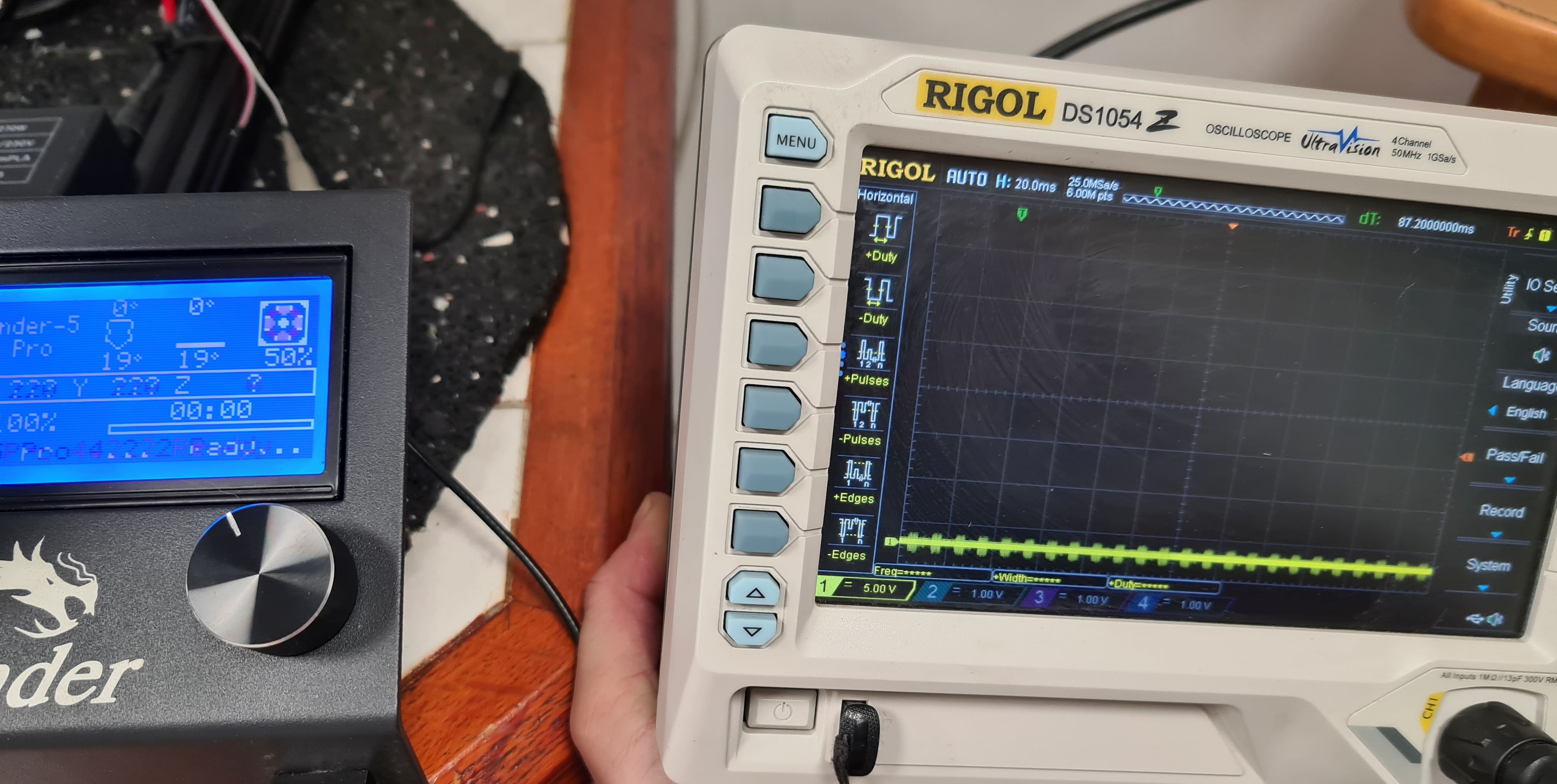
Software pwm is working alright however i need hardware pwm, because sw is only 7,8Hz which is too low for laser.
I think about two solutions possible:
EDIT: timer8 is not capable of generating PWM, so only timer5 could be used in replacement for timer2