Open ngarafol opened 4 days ago
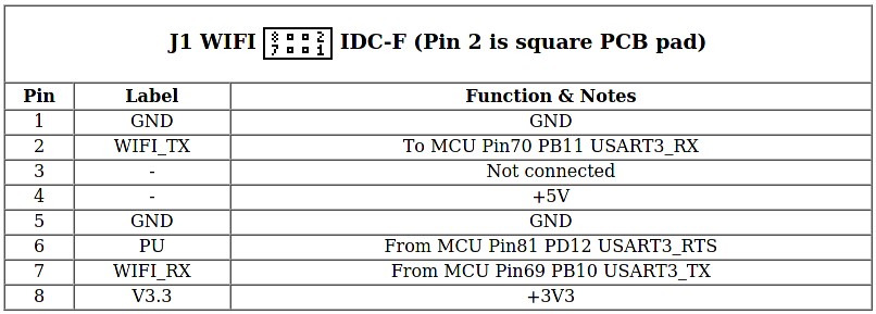
There are 3 IO pins on the wifi port from what I can see
PG1 // chip select (Pin6) PB11 // TXD (Pin5) PB10 // RXD (Pin4) - TIM2_CH3
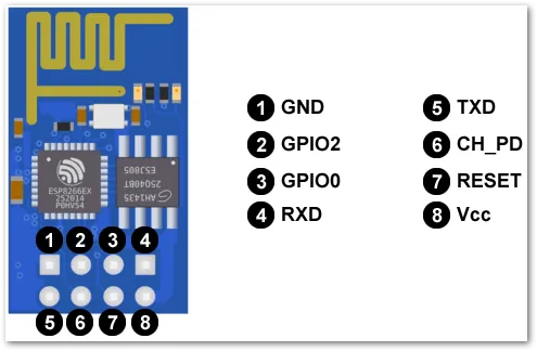
The wifi plug seems to be stock for esp-01 module
Note: the wifi is on UART 3, you must not set any SERIAL_PORT to 3 or it will conflict
Thanks for response @ellensp. I am using Pin4 for 5V, Pin6 for servo and Pin5 for GND. I believe I should set SERVO0_PIN to PG1 in that case, the one for pin6? Regarding serial ports, IIRC only port 1 is configured.
I followed this https://angryadmin.sesc.one/images/tronxy_wifi_pins.jpg from https://angryadmin.sesc.one/posts/tronxy-marlin/ (different revision of Chitu board, but still WIFI port should be the same).
you cannot use any IO pin. PG1 does not support hardware PWM
With SERVO0_PIN PB10, it is still behaving the same. Rebooting on its own when idle, or when I try to do Auto Home, it would home X and Y but Z is not moving (Z axis alone can be controlled). It returns to main screen, prints STOPPED and reboots again :( On initial flashing bltouch seems to work because it deploys two times (probably self test). Any tips what I could check?
first issue is https://www.antclabs.com/wiring says the bltouch needs 5v, and that ports supposedly only provided 3.3v bltouch manual says input voltage 4.8 ~ 5.1 V I suspect it will not run reliably on 3.3
The cpu is also on 3.3v, if you draw to much current, the processor will reboot. bltouch can draw a max of 300mA
yes that is a power on self test.
Use gcode to test the probe pwm signal.
Eg deploy the probe M280 P0 S10 stow the probe M280 P0 S90
the s parameter is the pwm value 0-255
Hm, seems you are correct again, Checked lines on WIFI1 and indeed PIN4 is giving 3.3V instead of 5V ... Is there any other 5V line on the board or should I wire dc-dc stepdown somewhere else to get 5V? Well, now that I think about it, better to wire dc-dc directly to PSU then, to stop stealing power from the board :)
I don't think there is any 5v on that board, but board details are thin and the manufacturer is not helpful. So all information is from 3rd parties...
I wired XL4005 to PSU directly, set it to output 5.1v. Connected BLtouch to it. But printer is still not ok. Rebooting and Z would not home at all.
@ellensp do you perhaps know what difference does it make to use pin7 for signal wire? I asked in FB group and one member said he used pin7 instead of pin 6, and following pins:
I used pin 4 for 5v, pin 2 (pb11) for z min, pin 7 (pb10) for servo0, and pins 1 and 5 for ground.
Did you test the latest
bugfix-2.1.x
code?Yes, and the problem still exists.
Bug Description
I cannot get BLTOUCH working with the board since PD12 pin is used by E2 stepper and I even tried PD13. Bltouch requires SERVO0_PIN defined and normally it would be pin 6 of WIFI1 connector board has, but with X5SA-2E model apparently it is not PD12 nor PD13. Configuration.zip
Bug Timeline
No response
Expected behavior
I would like that SERVO0_PIN for the board would be known :)
Actual behavior
I defined
#define SERVO0_PIN PD12
but it turns out in X5SA-2E printer it is used by E2 stepper according to https://github.com/MarlinFirmware/Marlin/issues/23761#issue-1143090197Steps to Reproduce
No response
Version of Marlin Firmware
bugfix-2.1.x
Printer model
Tronxy X5SA-2E
Electronics
other than bltouch, all stock
LCD/Controller
No response
Other add-ons
No response
Bed Leveling
UBL Bilinear mesh
Your Slicer
Prusa Slicer
Host Software
None
Don't forget to include
Configuration.h
andConfiguration_adv.h
.Additional information & file uploads
No response