 Dreamloom
commented
7 years ago
Dreamloom
commented
7 years ago Have you enabled pullups in the Delta config?
Closed Biggermens closed 6 years ago
Dreamloom
commented
7 years ago Have you enabled pullups in the Delta config?
 Biggermens
commented
7 years ago
Biggermens
commented
7 years ago yes I did I tried it all ways enabled, disable, I been a few day on this hehe what I don't get it works with one config file and not the other
 Bob-the-Kuhn
commented
7 years ago
Bob-the-Kuhn
commented
7 years ago Is that all that changed is the config files? My first impression is that the pin definitions have been modified.
If you ZIP them up and attach to your reply I'll do a compare and see if anything jumps out at me.
Also, please attach the sensor's data sheet (or a pointer to it). I'm starting to look into them & I'd like to see what others are using.
Biggermens
commented
7 years ago Hello there I really appreciate your help Thank you Ok hear is what I am doing now, so I don't get mixed up I downloaded RC8 bug fix.zip , I had best of luck with that one so far,( only one that the screen worked right ) I will set it up for my screen and limit switch's, and I will not touch nothing else. I did some testing all day and for some reason had a hard time reproducing my problem, nothing was working, RC8bugfix.zip my screen worked perfect but the proximity sponsor did not work at all, then I went to RC.zip and the same thing, :( I was getting discourage hehe, then I went back to my first firmware that I used 1.1.0 RC8,
Now I was kind of happy hehe they worked now, so I set them up as I would with a delta printer, X,Y Max and Z Max, Min, I did testing running M119 a bunch of time and it worked perfect. Then I put the Delta Generic Config files, setup the end stops the same at the regular send stops and now they don't work, :( hehe So the only way I got the proximity sensors to work was with the regular 1.1.0 RC8 firmware, with that firmware, my screen is very slow witch you fixed in RC8 bug fix.zip
Here are my parts list :) -Mega 2560 with a ramps 1.4 -Full graphic smart controller
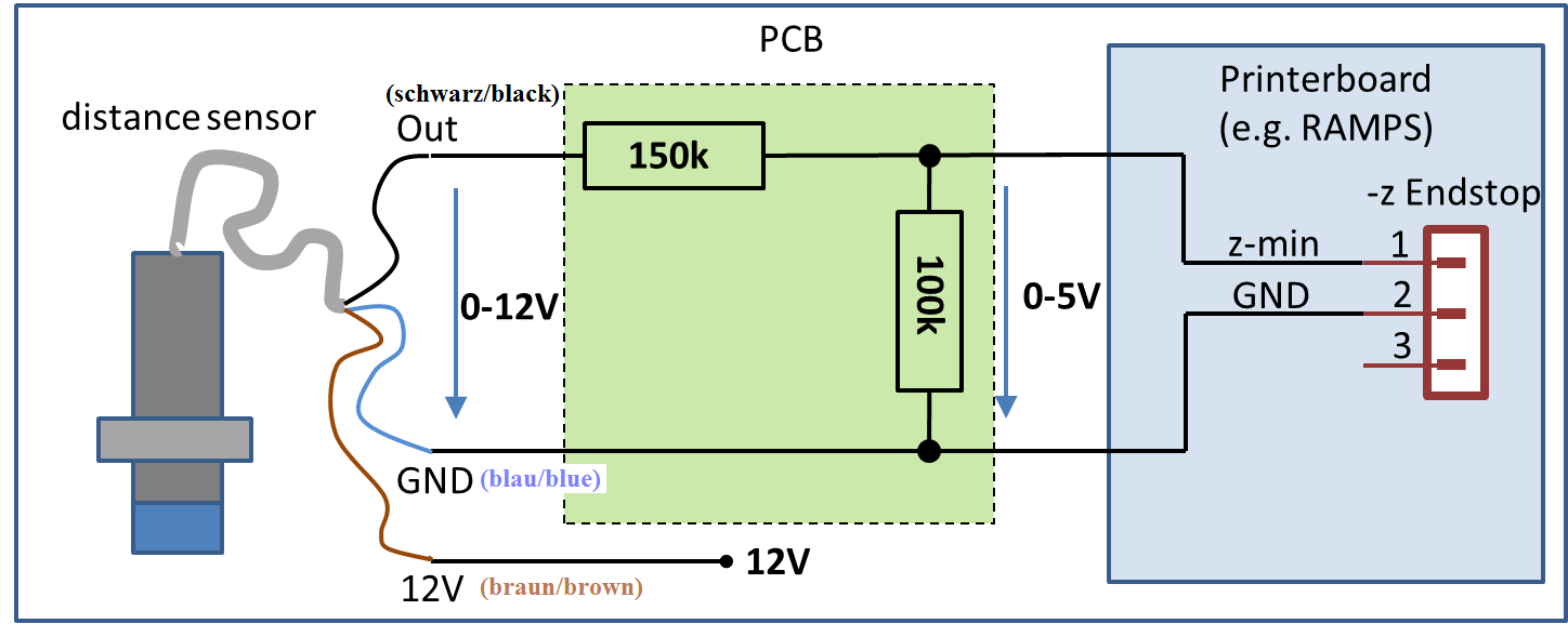
-For X, Y, Z, I used - LJ12A3-4-Z/BX Proximity switches http://www.banggood.com/TL-W5MC1-5mm-Detecting-Inductive-Proximity-Sensor-Detection-Switch-NPN-DC-6-36V-p-1089439.html?rmmds=myorder
-For Z Probe I used - TL-W5MC1 https://www.electronicgeek.ca/collections/3d-printer-electonics/products/sensor-induction-proximity-switch-lj12a3-4-z-by?variant=10535989123
I have them hooked up direct 12V from the power supply with a 150k and 100k resistor like this picture. http://www.3d-proto.de/public/img/IndSensorSetup.png
I did my best to find data sheets for this Chinese stuff hehe but I did my best
If you need more info let me know and again thank you very much :)
Marlin-1.1.0-RC8 (Delta not working).zip Marlin-1.1.0-RC8 (Working).zip [Data Sheets.zip] (https://github.com/MarlinFirmware/Marlin/files/836318/Data.Sheets.zip)
Bob-the-Kuhn
commented
7 years ago Have you put a voltmeter on the endstop signals and the black wires with your various configurations?
I believe your circuit is correct for the LJ12A3-4-Z/BX. I think the black/signal wire goes up to 12V on that one. You'll need to have the endstop pullups disabled (in configuration.h) for this type.
I think your TL-W5MC1 needs a different circuit. I expect that the black/signal on that one will only be at ground or , if the endstop pullup is enabled, 5V max. If that's the case then ditch both resistors, wire the black/signal directly to the endstop input and enable the endstop pullup. If it goes to +12 then your circuit is correct and you need to disable the endstop pullup.
I looked at both configurations. The #define ENDSTOPPULLUPS is different between them. That is probably why one works and the other doesn't. I think your delta configuration.h file should have //#define ENDSTOPPULLUPS in it.
Biggermens
commented
7 years ago Yes I did put a meter one the end stops and everything works correct on that part. But now I feel like a total idiot hehe I totally missed the line //#define ENDSTOPPULLUPS // I was playing with the one under it, and that did nothing
`#if DISABLED(ENDSTOPPULLUPS) // fine endstop settings: Individual pullups. will be ignored if ENDSTOPPULLUPS is defined //#define ENDSTOPPULLUP_XMAX //#define ENDSTOPPULLUP_YMAX //#define ENDSTOPPULLUP_ZMAX //#define ENDSTOPPULLUP_XMIN //#define ENDSTOPPULLUP_YMIN //#define ENDSTOPPULLUP_ZMIN //#define ENDSTOPPULLUP_ZMIN_PROBE
But now everything is working well, well kind of hehe but the limit stops are working grate :) I read somewhere to put a small diode on the signal wire, I tried that to see if it would change anything and it did not, They said the end stop will work better, Would you have any idea why ???
Again thank you very much :)
Bob-the-Kuhn
commented
7 years ago Glad to hear one problem has been solved.
Comparing files is not easy. I missed it the first time through even with using Notepad++ and it's compare plugin.
If you're getting false endstop hits then it's most likely due to noise on the signal line due to stepper cables or AC power cables being too close to the endstop cables. There's multiple ways of dealing with the noise. The diodes are one method. Some methods work in certain cases, others work in different cases.
Biggermens
commented
7 years ago OK right on, I have a bunch of diodes I will put them on for fun :)
Thanks again :)
Bob-the-Kuhn
commented
7 years ago Do you know how to orient them?
One goes from signal to +5V.
One goes from signal to ground.
Biggermens
commented
7 years ago From what I read the diode went inline with the signal with the anode on the ramps side, I am not a expert but I cant really see how it will help anything.
Bob-the-Kuhn
commented
7 years ago Agreed
Biggermens
commented
7 years ago Wouldn't a diode from +5 to ground make a short ?? or was that a resistor you were talking about ??
Bob-the-Kuhn
commented
7 years ago Here's how the diodes are usually used.

Biggermens
commented
7 years ago ok ic ic need 2 per limit stop, would it be a good idea to install diodes ??? I have a bunch laying around doing nothing hehe
Bob-the-Kuhn
commented
7 years ago If you're not having problems then I wouldn't bother.
 Roxy-3D
commented
7 years ago
Roxy-3D
commented
7 years ago Wouldn't a diode from +5 to ground make a short ??
Yes and no... It would depend on the orientation of the diode. Diodes only let current flow in one direction. If you orientate the diode such that the band is connected to the +5v side, no measurable current will flow.
Biggermens
commented
7 years ago That makes sense Roxy Thanks :)
I don't think I have this right with the example that Bob gave me, how that look guys??

Bob-the-Kuhn
commented
7 years ago The "+5V (Signal" should just say "Signal". The junction of the two resistors should go to just the endstop signal input.
The diode across the 100K resistor is correct.
The diode from ground to 12V MUST be removed. It's in the wrong location and it shorts the 12V to ground.
Biggermens
commented
7 years ago I don't really understand ?? "The junction of the two resistors should go to just the endstop signal input."
I don't think I changed much

Bob-the-Kuhn
commented
7 years ago 
Biggermens
commented
7 years ago I am starting to get a bit lots and feel a bit like a idiot here hehehe :( I am not sure this one is right now, What do I do with the other end of the 5 volts ?? one end on the ramps board and the other I am not sure. I hope I am not bothering you guys, I had a bitch of a time getting them end stops to work, I am just trying to get things clear and to give back, this 3d printer community is one of the better ones that I ever been part of, well is the better one, I am having fun :) Thanks again very much you guys

Bob-the-Kuhn
commented
7 years ago Graphics at 1AM is not my best talent.

Biggermens
commented
7 years ago Hehe its ok, hehe looks good now I just going to clean it up and make it a bit more clear and fancy :) I am going to guess that the diodes are there to isolate the ground from the signal and the signal from the +5V ???
 Blue-Marlin
commented
7 years ago
Blue-Marlin
commented
7 years ago These diodes limit the signal to 5V + forward_voltage_of_the_diodes and GND - forward_voltage_of_the_diodes. Typically the forward_voltage_of_the_diodes is 0.7V ( silicon diodes) (0.3 V for germanium and 0.2 V for Schottky).
Please compare: http://www.atmel.com/Images/Atmel-2549-8-bit-AVR-Microcontroller-ATmega640-1280-1281-2560-2561_datasheet.pdf Page 67 and 355.
The diodes do nothing useful - if not carefully selected.
Useful could be:
But usually the simple voltage divider is good enough here.
Bob-the-Kuhn
commented
7 years ago The diodes shunt high energy spikes to the power rails and keep the internal didoes within the Atmel chip from being over powered.
The Zener also protects the Atmel chip. It costs more and doesn't work as well as the two diode method.
The RC filter has been used. The vast majority of the time it's just a 0.001uF - 0.1uF cap.
The real solution is to either use shielded cable or separate the cables.
On my machine I used shielded cable for the steppers. Per recommendations from others I used Cat5 Ethernet cable and just cut off the ends. I used one pair for each stepper wire. You can get 100' of Cat5 for a really low price if you look around. I'm sure I'm loosing power because of the small gauge but I still have lots more than I need.
Bob-the-Kuhn
commented
7 years ago I must be really slow at composing posts - another one posted while I'm composing and I didn't notice it.
Agreed - you can definitely pick the wrong diodes.
Biggermens
commented
7 years ago Hehe is all good Bob :) I really appreciate all the help you guys doing :) This is now getting a little bit pass my ability's hehe I looked at the pdf and that was a lot, I can hardly read a Archie comics hehehe I read what you guys wrote a few times and did some goggling to try to understand more and I cam up with this I appreciate all you guys patients also :)
How that look ?

Bob-the-Kuhn
commented
7 years ago That'll probably work.
Biggermens
commented
7 years ago Right on :) Thanks Man I will make my drawing a bit better :) Call me crazy but I always wanted to make a little website documenting some of the things that I built but never did, I think I will do it with this 3d printer things, the more detail the better, I find lots of video and forums there are always missing a little something, I would make it as clear a day :) hehe I will call it How I Did It hehe that sound crazy ???
Biggermens
commented
7 years ago Probably make a few YouTube video also
Bob-the-Kuhn
commented
7 years ago :-)
Blue-Marlin
commented
7 years ago An other tip is to place the voltage divider as close as possible to the controller board. On the, then longer, 12V section the signal noise ratio is much better. Additionally the caught noise (like the signal) is reduced to 2/5.
Biggermens
commented
7 years ago Hey Bob I just went out and bought www.ThatsHowIDidIt.com hehe I am going to try some of that free hosting and see how it work :) I will post my 3d printer build and all the other stupid things I do hehe Thanks again everyone for all your help :) Keep in touch :)
 github-actions[bot]
commented
2 years ago
github-actions[bot]
commented
2 years ago This issue has been automatically locked since there has not been any recent activity after it was closed. Please open a new issue for related bugs.
I have a mega 2560 with a ramps 1.4 and a Full graphic smart controller I tried a few of the RC version of marlin and with the regular config files the limit switches work fine and when I use the delta config files they no longer work. with the regular config files I get 5v and 0.2 when triggered and it works when I send a m119 with the delta config file I get 5v and 3v when triggered
I don't understand :( hehe Thanks everyone