MarlinFirmware / Marlin

Marlin is an optimized firmware for RepRap 3D printers based on the Arduino platform. Many commercial 3D printers come with Marlin installed. Check with your vendor if you need source code for your specific machine.
https://marlinfw.org
GNU General Public License v3.0
16.26k stars 19.23k forks source link

[FR] Z offset not same on all bed using Bilinear #9187

Closed VincentWiz closed 6 years ago

VincentWiz commented 6 years ago

Bug Report

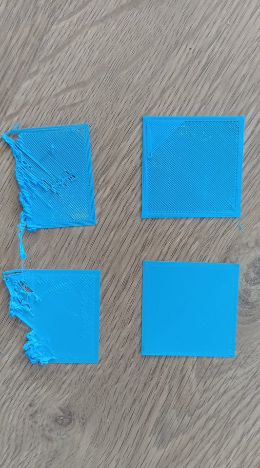
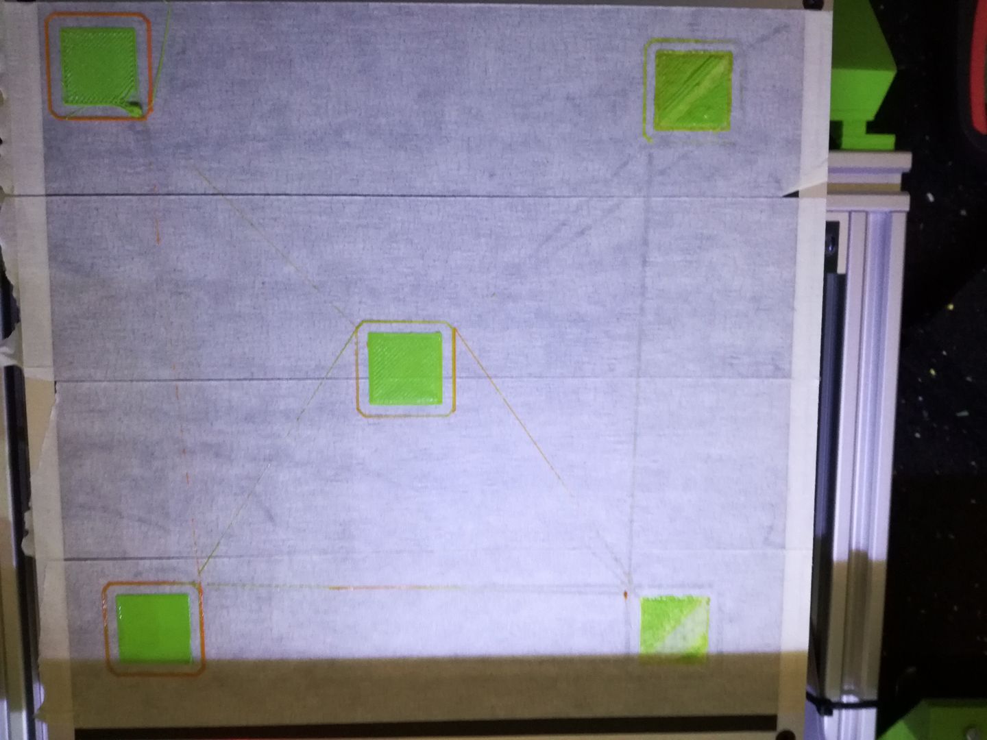
With capacitive sensor 26229987_10212268008949540_3942964468883018005_n

With BLTouch 26240188_10215077444199191_4501844852091863261_o

AnHardt commented 6 years ago

@VincentWiz Our bed tramming algorithms try to keep the distance bed-probe constant. This works pretty well as long the distance between nozzle and probe is constant. X-rotation prevents that https://github.com/MarlinFirmware/Marlin/issues/9529#issuecomment-365298112 and follwups made this a bit clarer to some.

@filipgoc Right. Almost everything can be fixed in software. The question here is if it can be done in the time we have and where can we get the needed data. This is a nonlinear problem. Until someone finds a trick we'd have to calc a sin() and or cos(). Because a similar problem exists for Y the amount of calculations will grow fast. (An idea could be to apply the correction not to every point we go, but only to tune the mesh (if we have one)). An alternative for hand tuning the mesh. While thinking about it - hand tuning the UBL mesh is the procedure to get the required data.)

@thinkyhead Somewhere else you talked about a test to compare the probes result with a nozzle-paper-test in the mid of the bed to find the Z_PROBE_OFFSET_FROM_EXTRUDER. For debugging purpose a way to make this test at X Y or at the current position would be nice.

filipgoc commented 6 years ago

@AnHardt Good point. Though, at some point, the real question does become what is desirable to fix in software, as you hint towards. A dramatic rephrasing of the thought:

"We fixed it, sonny." (Long dramatic pause. Camera zooms in on the programmer's face, visibly in pain. Trying not to cry.)

"But at what price...."

(Breaks down crying. Camera gently pans away and up into the sunny sky that offers a stark contrast to the emotional darkness of the scene. Cut.)

Roxy-3D commented 6 years ago

The question here is if it can be done in the time we have and where can we get the needed data. This is a nonlinear problem. Until someone finds a trick we'd have to calc a sin() and or cos(). Because a similar problem exists for Y the amount of calculations will grow fast. (An idea could be to apply the correction not to every point we go, but only to tune the mesh (if we have one))

If we decided to fix this in software... We probably don't need to do the sin() and cos() computation at each point. We could apply the mesh concept to the twist also. At any given location, we could be within a mesh cell that holds accurate sin() and cos() values for the twist at that location. And probably, we could do the interpolation. (It maybe it doesn't even need to be bi-linear. It maybe the bulk of the correction can be done on each individual axis.)

We would also have to figure out accurate ways to measure the twist so the correction data could be loaded and used...

For right now... It seems more reasonable to have the requirement the machine is built properly.

thinkyhead commented 6 years ago

When we add the "too much deviation" test, Marlin will simply reject a mesh that is obviously wrong. But I fear there is no general solution to work around a weird gantry or off-angle probe. Sometimes the little wheels that the carriage rides on are a little off, and then your mesh comes out "lumpy." I don't think we can fix that automatically either.

filipgoc commented 6 years ago

The 'too much deviation' reminds me of missing points. Sometimes, points end up missing and can be easily filled in with G29 P3. Maybe a warning that there are missing points and that G29 P3 (or redoing the probing) would be prudent. If one runs with some terminal and can see the topology, this is not that big a deal, but over the LCD, it's not easy to see if the mesh is all filled in. Or is there an easy way I'm missing ?

EDIT: disregard, this is UBL. I got threads confused.

filipgoc commented 6 years ago

A follow up question to that... why would points be missing in mesh? If I do automatic probing, the probe does correctly sense the bed, and it works most of the time, why would every now and then the probing come back with one or two missing points in the mesh?

I have observed this behavior, but didn't realize it may be a bug or something.

EDIT: disregard, this is UBL. I got threads confused.

thinkyhead commented 6 years ago

Whenever there are homing or leveling issues, we now ask everyone to follow a standard procedure to gather more information so that we're not just taking stabs in the dark. Here is the boilerplate:

Repeat this procedure, if needed, to demonstrate inconsistencies. From these logs we should hopefully get a better idea of what's going on with your machine.

You can use M114 D as you move around the bed to see lots of details about the current position. If you see strange things, also copy them into your text file.

Since you're using BILINEAR leveling, you can also use G29 Q at any time to see details about leveling at the current position.

We look forward to your next report. Hopefully we can narrow this down to a single cause and fix it.

filipgoc commented 6 years ago

Sorry, I got threads confused. The missing points fun is from UBL. (I'm using/ testing both UBL and Bilinear ABL).

github-actions[bot] commented 3 years ago

This issue has been automatically locked since there has not been any recent activity after it was closed. Please open a new issue for related bugs.