 NeoCat
commented
5 years ago
NeoCat
commented
5 years ago It might be because not enough power is provided. USB serial is not good power source. Use external power source such as an AC adapter that can provide at least 2A current.
Closed GeorgeFlorian closed 5 years ago
NeoCat
commented
5 years ago It might be because not enough power is provided. USB serial is not good power source. Use external power source such as an AC adapter that can provide at least 2A current.
 GeorgeFlorian
commented
5 years ago
GeorgeFlorian
commented
5 years ago It might be because not enough power is provided. USB serial is not good power source. Use external power source such as an AC adapter that can provide at least 2A current.
These are the specs of my power supply:
https://i.postimg.cc/prt2vnW7/20190401-145102.jpg
I am using 2 Logic Level Converters to shift from 5V to 3V3.
NeoCat
commented
5 years ago Or, you might have burned your flash. Check here too: https://github.com/espressif/esp-idf/issues/117
GeorgeFlorian
commented
5 years ago Or, you might have burned your flash. Check here too: espressif/esp-idf#117
How can it be burned if I can upload sketches and use the ESP32 when I take it off the board and power it up using a USB Cable ?
NeoCat
commented
5 years ago The error is reported at many pages, but I'm not sure why you are suffering the issue. It might be due to your board broken by electrical shock or mis-write the fuse bits, or power source issue, or short in your circuit, or many other reasons. What I can say is only that google by the error message and try many things with your hardware...
GeorgeFlorian
commented
5 years ago The error is reported at many pages, but I'm not sure why you are suffering the issue. It might be due to your board broken by electrical shock or mis-write the fuse bits, or power source issue, or short in your circuit, or many other reasons. What I can say is only that google by the error message and try many things with your hardware...
Do you have any photo of one of your wiring to the LED Display ? I am convinced I soldered the wires appropriately, but having no example and this being the first time doing it, I may have done something wrong.
NeoCat
commented
5 years ago GeorgeFlorian
commented
5 years ago Hope this helps... https://cdn-ak.f.st-hatena.com/images/fotolife/N/NeoCat/20180502/20180502032100.jpg
Dude, this is great ! You have way less wires than I do. I used 2 LLC to shift from 5V to 3V3 but you don't. You connected the GPIO from the ESP straight to the HUB75 and you feed 5V to the ESP... How ? Isn't the ESP supposed to work at 3V3 ? You have nothing connected to the 3V3 pin..
NeoCat
commented
5 years ago I am driving the LED matrix directly by the 3.3V signals, but working without any problem so far. The power source is 5V 2A-max AC adapter.
GeorgeFlorian
commented
5 years ago I am driving the LED matrix directly by the 3.3V signals, but working without any problem so far. The power source is 5V 2A-max AC adapter.
I don't know how you did that ! I used Logic Level Converters and it still burned my ESP32.
 carloHuang
commented
10 months ago
carloHuang
commented
10 months ago Maybe you can check if the esp32 strapping pin is set to the wrong state.I've encountered similar problems.IO12 should be pulled down by default, but my baseboard pulls this IO port up to 3.3V with a resistor.
Hello !
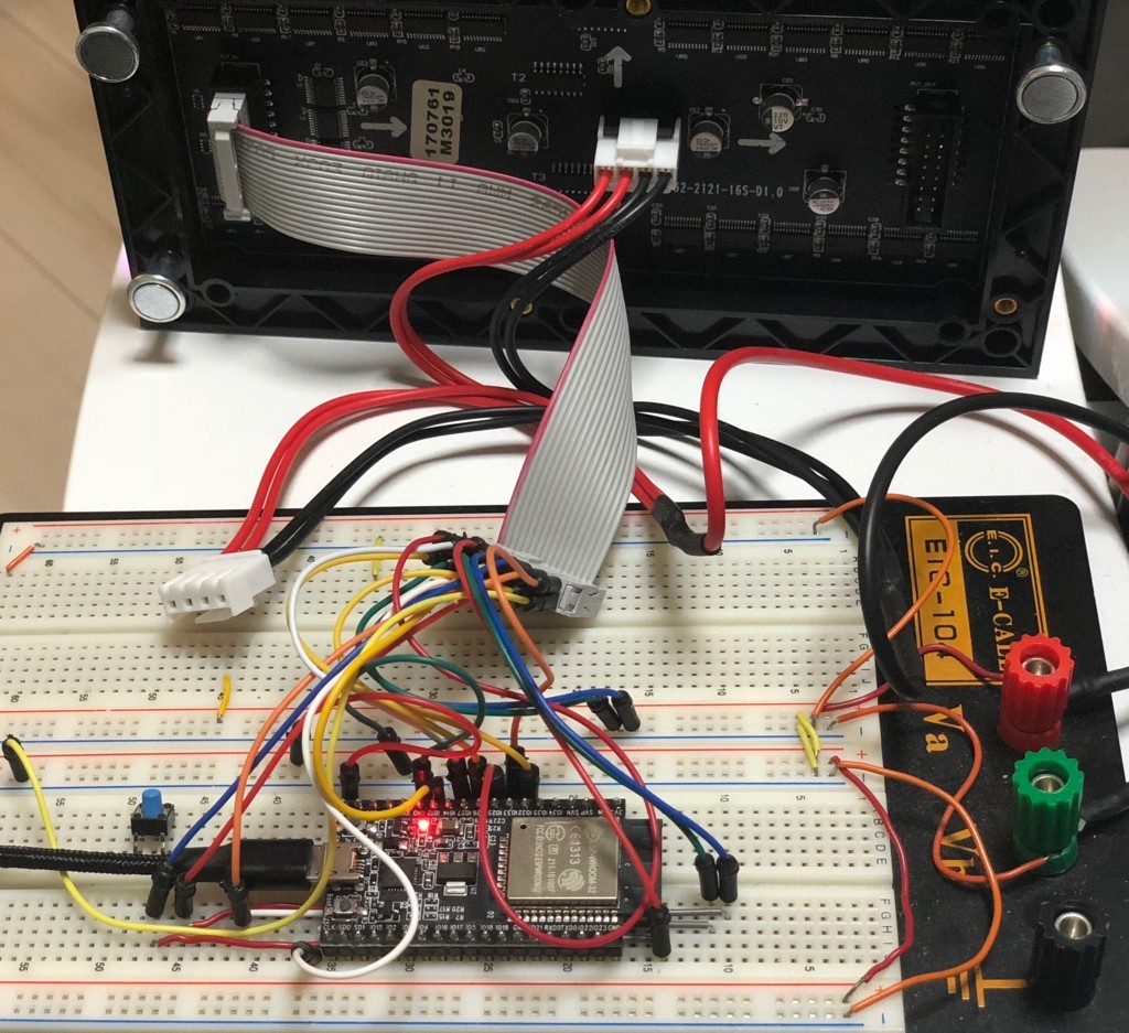
I'm using an ESP32 Wroom-32, a SMD 2727 P5 64x32 LED display and 2 Logic Level Converters.
I've soldered the pins as per the default constructor. I've uploaded the following sketch in the ESP and something bizarre happens.
https://i.postimg.cc/VkCHqbsd/20190401-135241.jpg
The RED (PIN 1) wire from the HUB75 is on R1 (IO25).
I've done the workaround, changing from
PROVIDE ( GPIO = 0x3ff44000 );toPROVIDE ( GPIO = 0x60004000 );If the ESP32 is half-way inside (like this), the screen is white if I insert it all the way it get's red
If I reset the ESP, the display will be off, and the Serial Monitor will output:
repeating itself without stopping.
If you are wondering why I need to insert the ESP32 into the board every time it's because I can't upload a sketch when the ESP32 is on the board.