Nuand / bladeRF

bladeRF USB 3.0 Superspeed Software Defined Radio Source Code
http://nuand.com
Other
1.15k stars 462 forks source link

Problems with signal reception (BladeRF-x40 , GNUradio) #875

Closed raul8883 closed 9 months ago

raul8883 commented 2 years ago

Hi everyone, I am having problems when I receive signals using two SDRs (BladeRF - x40), one to transmit and one to receive (I know I can transmit and receive using 1 SDR, but I need the complete schematic transmitter, receiver), the problem is the following, I have a complex signal , with the following values: in-phase component (i(t)) tx = Ac * x(t) quadrature component (q(t)) tx = 0 Vy (t) tx = i(t) + j q(t) TX image I send this signal to the channel and therefore it is received by the SDR receiver. What I receive in the reception is not similar to what I transmitted, because of a tone appears both in its component in phase and in quadrature, by making q(t) rx /≈ q(t) tx /≈ 0. RX image For a better compression, I will transmit the following signal x(t) = 0 (equivalent to i(t) tx = 0, q(t) tx = 0), so in theory in reception it would only have noise, but this is not the case. TX image RX image When I use a single SDR to transmit and receive this does not happen, I don't know if this is due to some kind of synchronization, but with this problem I can not correctly classify the type of modulation. BLOCK SDR Transmitter. image BLOCK SDR Receiver. image
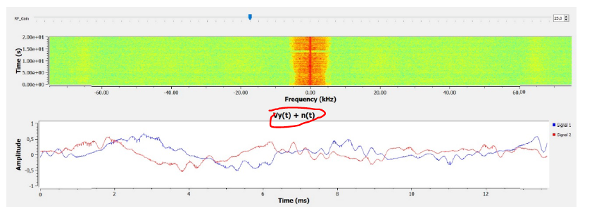
This is what i am getting (Frecuency Domain) when i am transmitting a message with amplitude = 0 and both SDRs have gain equal to 0 image

When I increase the gain, that peak increases, in addition another peak appears symmetrical to that one with less amplitude image

This does not happen when I transmit and receive with the same sdr, Could this be due to mismatches between both SDRs?

I need help to know how to make it not transmit and receive that unwanted signal. Thank you very much in advance!

raul8883 commented 9 months ago

I did not remember that I left this thread open :) I will proceed to close it after recording what happened as well as its solution. If I remember correctly, to implement the solution I relied on a Web which I left referenced in my final thesis.

On the other hand, depending on the application for which you specifically use two bladeRF SDRs (since using one as tx and rx this does not happen) this may or may not be a significant problem, clarifying that whenever you use two bladeRF SDRs this problem will probably be present.

raul8883 commented 9 months ago

PROBLEM:

The problem was due to what is called IQ unbalance, specifically of the three types of IQ unbalance that we can find the one that affected us in question was the one called ’ Direct Current (DC) Compensation’.

This problem exists due to the local oscillator, leading to a deviation of the received samples, i.e. there is a miscalibration between the frequency of the signal generated by the oscillator of the transmitting channel of SDR number 1 and the frequency of the receiving channel of SDR number 2, where, for the same SDR, both channels are calibrated. The carrier generation is performed by the same local oscillator for both directions of communication, transmission and reception. The following is a detailed description of the above for a better understanding compression. The bladeRF has two channels, one for transmitting and one for receiving, both channels of the same SDR use the same local oscillator for modulation and demodulation, simply one of the two generated signals will be out of phase “90º” with respect to the other, both channels of the same SDR are calibrated to each other, this does not mean that, if you transmit for example at the carrier frequency of 915 MHz, you are transmitting at exactly that frequency. The same applies to the receiving channel, that is receiving at 915 MHz, does not imply that just is received at that frequency, being able to transmit and receive for example at 915,000,100 Hz, here is where the concept of calibration comes in, and that is that, using the same local oscillator for the transmission and reception of signals, even if exactly neither transmitting nor receiving at 915 MHz, there will be practically no deviation in the received samples, since the oscillator used for carrier generation with that small frequency error is the same used for modulation and demodulation, i.e., that small frequency error is being assumed in both directions of transmission for the same SDR. The use of two SDRs, however, could result in having a different error in the frequency of the generated carrier signal, i.e., if you are transmitting with an SDR at the frequency of 915 MHz (actually at 915,000,100 Hz, for example) and you are receiving with a different SDR at 915 MHz frequency (actually at 915,000,300 Hz, for example), a deviation in the received samples is occurring, which is what is happening with the transmission and reception of signals using two SDRs.

raul8883 commented 9 months ago

I comment first that the solution if I remember correctly could be implemented with an automatic calibration, however I opted for a manual calibration by using GNU radio, also if you want to try the automatic calibration you can access the Web that I have as reference [40] in my final thesis that I will leave it in this thread.

SOLUTION:

The solution will be based on the following:

By using GNU radio, two computers and, two SDRs, it shall be transmitted and receive simultaneously signal values equal to 0.

Using GNU radio, a block will be used in the reception scheme, which allows the carrier frequency of the receiving SDR’s receiving channel to be varied over a range of values. The receiving SDR’s receiving channel carrier frequency can be varied by means of a predefined range of frequency values.

By means of GNU radio, the frequency spectrum of the signal being received will be displayed in real time, localizing The frequency spectrum of the signal being received in real time, locating the DC peak originated by the mismatch between transmitter and receiver.

Next, adjust the carrier frequency at the receiver while viewing the received spectrum, trying to calibrate between the received spectrum is displayed, trying to make the calibration between both SDRs, thus trying to reduce the observed DC peak. both SDRs, thus trying to reduce the observed DC peak.

Finally, the existing frequency error between the carrier frequency at which it is transmitted and the carrier frequency (corrected) at which it is actually received will be noted, so that, whenever a simulation is performed, the corrected carrier frequency is received.

Screenshot_20240228_014918.jpg

Where: fc(corregidaRX) is the carrier frequency to be used in reception to achieve calibration between SDR transmitter and SDR receiver.

fc(RX) Is the ‘assumed’ carrier frequency at which it should be received.

fc(realRX) is the carrier frequency that is actually received.

Being the error or fc(offsetRX) Screenshot_20240228_015452.jpg

Screenshot_20240228_015545_com.google.android.apps.docs_edit_556523126906226.jpg

raul8883 commented 9 months ago

Finally and as I said before I will leave here my thesis, where the reference [40] corresponds to the web site commented before, likewise, from page 112 I comment in detail this problem as well as others that could affect us and its solution from GNU radio.

If you have doubts about anything related to artificial intelligence (specifically machine Learning), SDRs, modulations, or anything else related to signal processing, etc..., do not hesitate to ask me, although I am currently quite busy, I will try to do my best :)

https://drive.google.com/file/d/1wBhhZ_Pr2xIqFWOrnK2f2ufZM4sRHEgE/view?usp=drivesdk

By the way the thesis is in spanish but you can translate it.

Greetings to all, I hope it helps. 🤗🤗