 DanD222
commented
4 years ago
DanD222
commented
4 years ago My two cents..
Regarding point 3. - separate regulators for each sensor please. However, are we sure about the ferrite after the regulator, like in the original sensorboard schematic? I would expect it to be pre-regulator, to better decouple the regulators from each other, and to not increase high frequency PSU impedance to the sensor?
Audio amp - I wanted to suggest the PAM8303 / PAM830 line for consideration as these can be hand soldered, but given that this won’t be possible for a lot of the components you’ve mentioned, it’s probably a moot point (same goes for through-hole electrolytic capacitors).
Regarding additional point 2 - I would love this to be able to live inside an OV as a drop-in replacement, but also to be able to exist on its own, feeding airspeed and vario data to XCSoar running on a mobile phone.
Regarding additional point 6. - I’ve wondered whether you could get air leakage from a via to a pressure sensor when using bypassing on the bottom side close to the sensor..?
 hpmax
hpmax iglesiasmarianod

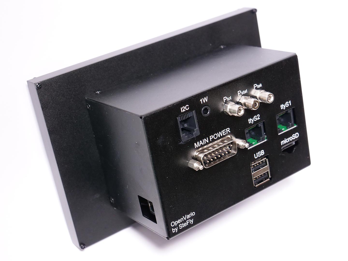
 Those are TTyS0. It is not used to connect external devices. You'll find them wired to two DB15 connector pins 2 and 10.
 Those jumpers connect Cubieboard's serial pins to DB15 pins.


I figured I'd start a new comment to discuss the second gen sensorboard. My proposed hardware at this point is:
1) LPS22HH (replaces MS5611). I really don't know which is better, but the LPS22HH is a LOT cheaper, and may actually be superior. It's worth testing.
2) MS4515DO (replaces AMS5915). Again, I don't know if its better, specs are slightly better, it's a little cheaper, and more available (at least in the United States). It's worth testing.
3) NCV8163 (NCP163 also seems to be a pretty equivalent part, replaces MCP1700) Slightly more expensive, and higher quiescent current (but still trivial compared to its load), it's smaller and spec-wise blows the doors off the MCP1700. Electrical noise is reduced by at least 30dB both in terms of PSRR and output noise. This is a DRAMATIC improvement. An open question on this is how many do we want? One for each sensor? Using independent regulators both improves PSRR and decreases cross talk noise on the supply.
4) ESP32-WROOM-32E Timo suggested it, I'm willing to go with it. I am a bit concerned about how much power it can consume, but I presume it's only consuming massive amounts of power when it's doing something useful.
5) LDL212PV33R... regulator for the ESP32. An NCV8613 could probably do the job, but they have a 250mA max, and aren't real good about dissipating power -- and the documentation I've seen on the ESP32 says you want a 500mA power supply. For manufacturing and cost reasons, it would be nice to stick with all one type, but oh well...
6) DS2482 (carried over)
7) LSM6DSM and MMC5983MA (replaces the MPU9150) The 9150 is long obsolete, the 9250 that replaced it is obsolete too. I spoke to Kris Winer who has a lot of experience testing different parts. Those were his recommendations along with the LPS22HH
Some additional comments/thoughts:
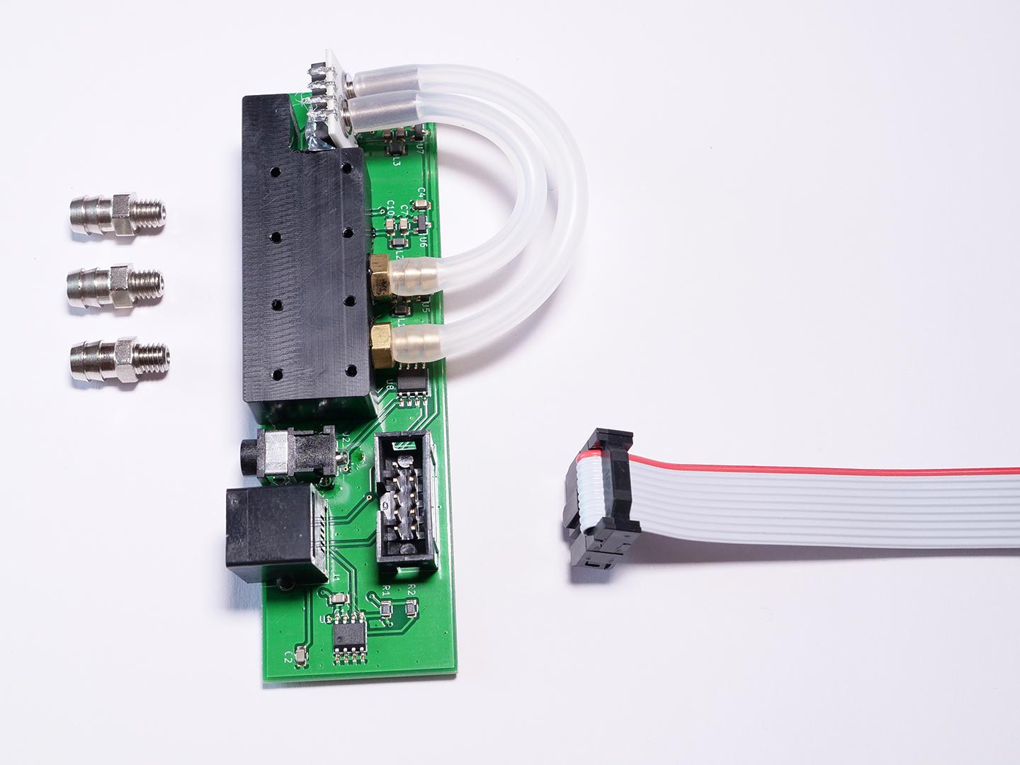
1) Is there supposed to be an audio amp on the sensorboard? The one I got from Stefan has the amplifier on the adapterboard. Regardless, I'd be inclined to replace the AS1701. Stefan is using the MAX9718A which seems to be a reasonable choice. The MAX98304 is a really nice Class D amplifier. Downsides are that you can't get more than 12dB gain out of it, and that its Class D and hence may emit noise. I'm building up an amplifier board now based on the MAX98304 and I think I can knock the EMI down by at least 60dB over all the frequencies I'd care about (IF, RX+/-IF freq) over already good results, and the 98304 is quiet to begin with by Class D standards. So I'm hoping it'll be okay. Otherwise, the MAX9718A is a decent choice, but it does have heat dissipation issues.
2) Do we want a drop-in replacement for the current board, or should this be an external unit which could interface to other things (for example a direct vario display) -- if so, how do we interface to the OV? One other possible choice here is the ESP32-S2, which is allegedly cheaper and lower power and supports USB. Downside is you also lose a core, and some memory, and Bluetooth. But allegedly the newer process is faster at floating point, which is what this thing is going to spend most of it's time doing. I like the notion of this being an external device that could directly receive GPS input, and directly drive an external display and then provide the OV with a complete IMU interface.
3) The new board is almost certainly going to be larger. The main driver for that is the ESP32, but there's just going to be more stuff on it period. I think there's plenty of room in the case, but I do worry because I think it's only held in place by the fitting screwed into the POM block. I don't know if this will cause a moment issue if the board extends further away from the end of the case.
4) Does anyone have a files with the board layout? I'd like to keep the sensor components in the same relative location so that the POM block can be reused.
5) EEPROM? I'm not sure what the point is. I'm not even sure what the point is in the current version. The data could just be stored in the configuration file (and in fact, it already is, so the EEPROM is just another compensation on top of the pre-existing compensation).
6) Anyone have any thoughts about putting components (capacitors in particular) on the bottom of the board? I want to be able to bypass the sensors under the POM block without interfering with the POM block.