 dyamon
commented
2 years ago
dyamon
commented
2 years ago What we are using is probably not the best setup for the robotic arm design we are going for.
Overheating problems and pulse on high current
From a RepRap forum post:
"Looks like the current is set too high to me. They run OK for a while until the chips get too hot and start cutting out, cooling a little and cutting back in. That is the pulsing effect you see in the second half of the video."
The video is not available anymore, but we have the same behaviour. From the docs:
"[A4988] offers overcurrent protection. If the boards get too hot, they will interrupt the current until it cools a bit. If the current is too high for the heat sinking, the motors will pulse as the current is interrupted and restored."
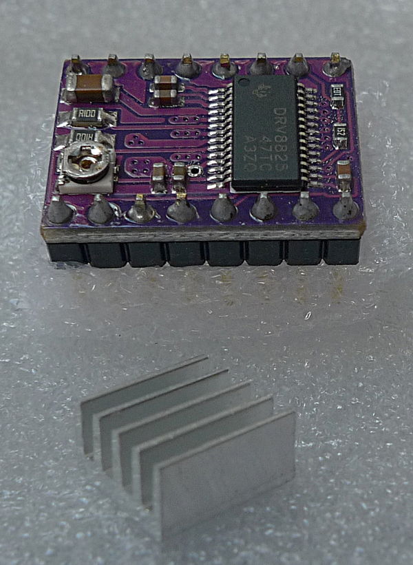
Also, about the heat sinks:
"[...] the use of some thermal conductive glue makes things easier. Try Arctic Silver - Arctic Alumina Thermal Adhesive or similar."
The effect of the small heat sink is debatable. Some people think it actually improves the performance of the driver, while RepRap highly recommends active cooling.
How to properly compute Vref
Vref refers to the voltage value that can be regulated through the small potentiometer on some drivers (e.g., A4988, DRV8825).
In order to set the value correctly you need to take into account a couple of parameters:
-
The rate current for the stepper motor (you can find it on the component or the datasheet).
-
The value of the current sense resistor (here is a nice intro to current sense resistors). They are usually marked on the sink screen as S1/S2 and typical values are 50mΩ, 100mΩ, 200mΩ. See close ups for A4988 and DRV8825.
Once you have all the necessary info you need to refer to the driver datasheet.
Consider this datasheet for A4988. It mentions that the driver has an internal PWM Current Control for which the maximum trip current $I_{MaxTrip}$ can be computed with the following formula:
\begin{equation} I{MaxTrip} 8 R{S} = V_{ref} \end{equation}
where $R{S}$ is the value of a single current sense resistor. If we set $I{MaxTrip}$ as the rated current for the stepper motor we can get the ideal value for Vref.
Example:
Assuming we have a rated current of 2.8A (e.g., from our NEMA 23) and a current sense resistor of 100mΩ we get
\begin{equation} 2.8A 8 0.1Ω = 2.24V \end{equation}
Note: this voltage value might not be compatible with the driver. In this case, our A4988 can't even provide this value of Vref.
Similarly consider this datasheet for DRV8825. In this case the formula is slightly different:
\begin{equation} I{MaxTrip} 5 R{S} = V_{ref} \end{equation}
Example:
Similarly, assuming we have a rated current of 2.8A and a current sense resistor of 100mΩ we get
\begin{equation} 2.8A 5 0.1Ω = 1.4V \end{equation}
This is more or less what we observed during our experiments. We initially found that a value for Vref of 1.5 was giving good performances but we should be able to lower the value more.
Motor drivers used in the MoveoArm
According to this infamous picture and the building manual, the MoveoArm uses the TB6560 motor drivers. Since our electronics setup is inspired by the one from the Moveo, it would be ideal to stick to this choice.
According to the pictures in this datasheet, all the information necessary to setup the driver and limit the current flowing in the motor is reported in the silk screen.
Shoulder motors
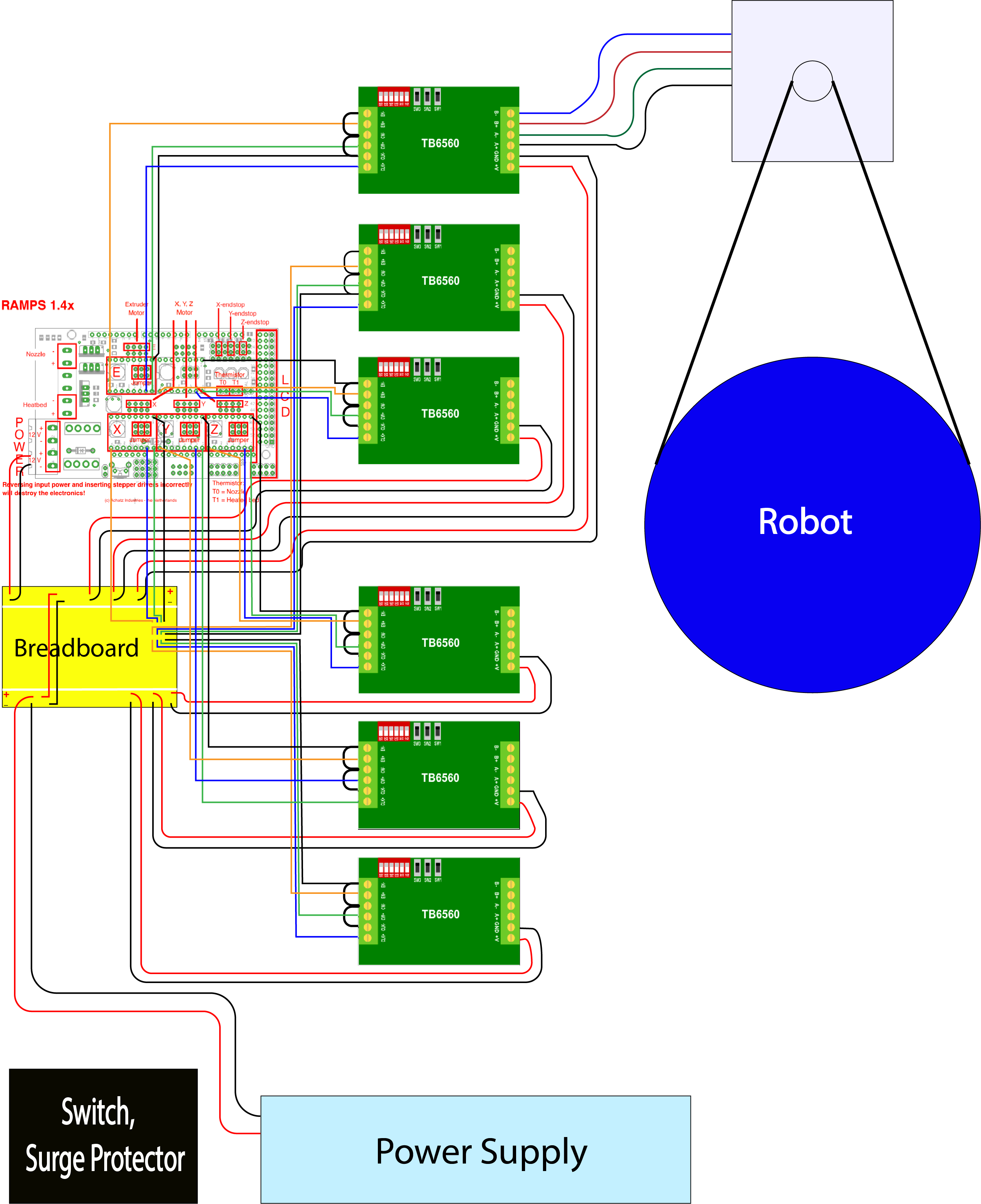
The shoulder of the arm (at the base) is powered by two NEMA 23. So far we have used two different "slots" in the RAMPS 1.4 to power two drivers (and motors), syncing them and setting the correct direction via software. The plan was to eventually use the same driver to power two motors, inverting the signal from the hardware side.
IMPORTANT: this is not possible! This is creating a simple parallel circuit (two motors in parallel, with the power supply as a source in series with the driver). Let's assume the rated current for a single motor is 2.8A; since the total amperage flowing through a circuit is the sum of the currents of each branch, we would need a driver providing $2.8A * 2 = 5.6A$ to supply two identical motors in parallel with the correct rated current (TB6560s are not able to do that).
The solution is to use two drivers, put in parallel with the motors. At this point, the source in the circuit is simply the power supply which should be able to provide enough current to both drivers (and hence to both motors).
TB6560 setup
First of all, the driver needs to be set up using the dip switches on the board. The silk screen on the driver should give you all the information necessary to configure it.
Example:
In order to provide the correct rated current (let's say we are aiming for 2.8A, the rated current for our NEMA 23), we can set the driver to provide 3A. The "running current" table tells us to set SW1, SW2, SW3 to on and S1 to off. We should proceed similarly with the rest of the switches.
Keep in mind the terminology:
-
Running current should be as close as possible to the rated current of the motor, to maximise performance;
-
Stop current is the current used to hold the motor shaft at a stopped position. You will want to set this as low as possible, to minimize unnecessary heating of the motor. Increase this value if your motor cannot hold its position.
-
Excitation mode is equivalent to the number of microsteps.
-
Decay seems to be the speed at which the magnetic field in the motor decays, but I'm not really sure about this. Some people on the interwebs suggest to leave it at 0%, while others set it to 50%. In the end, it shouldn't matter for our setup.
Finally, have a look at the picture to connect the driver to a RAMPS 1.4. Note that cable colors don't necessarily have any meaning and you should check with a multimeter for continuity to find out the couple of cables A+/- and B+/- that connect the driver to the motor (or alternative look at the current connections and try to remember the order of the colors).

Arduino code
We should be able to use the code we have been using so far.
In particular instances of AccelStepper should be created in the same way, with unaltered pins setup.
Enable pin still needs to be set to LOW (inverted pin).
 Vigo-Falcrum
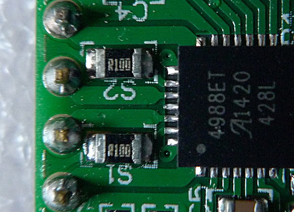
At the time of writing, some of the stepper motors don't seem to be able to support the weight of the arm. This might be due to the fact that we are not providing enough current to the motors by setting the limit too low on the driver.
Experiment with this.