Pi4J / pi4j-v2

Pi4J Version 2.0
Apache License 2.0
269 stars 55 forks source link

MCP23017 as GPIO provider example #138

Open tatery opened 2 years ago

tatery commented 2 years ago

Hi,

First of all a big thank you for your great effort in releasing the pi4j v2 library, you did an amazing job.

I'd like to use the MCP23017 as a GPIO provider, but the codes you posted as examples are very simple and in some cases confuse me. For example: https://github.com/Pi4J/pi4j-example-minimal/blob/main/src/main/java/com/pi4j/example/MinimalExample.java

        // Here we will create I/O interfaces for a (GPIO) digital output
        // and input pin. Since no specific 'provider' is defined, Pi4J will
        // use the default `DigitalOutputProvider` for the current default platform.
        var ledConfig = DigitalOutput.newConfigBuilder(pi4j)
                .id("led")
                .name("LED Flasher")
                .address(PIN_LED)
                .shutdown(DigitalState.LOW)
                .initial(DigitalState.LOW)
                .provider("pigpio-digital-output");
        var led = pi4j.create(ledConfig);

You wrote: "Since no specific 'provider' is defined" but some provider is there: ".provider("pigpio-digital-output")". BTW: how do I know what strings you predefined to put in the provider (e.g. to avoid the same strings in my custom implementations)?

I tried to create MCP23017 as my custom provider, but unfortunately I was not successful. The documentation is very limited and there is no complete example of how to create such a provider. Could you please help and create an example of an "advanced IO provider"?

Many thanks in advance.

savageautomate commented 2 years ago

You wrote: "Since no specific 'provider' is defined" but some provider is there: ".provider("pigpio-digital-output")". BTW: how do I know what strings you predefined to put in the provider (e.g. to avoid the same strings in my custom implementations)?

The provider implementation is not fully completed yet. We are missing some of the Linux file system provider implementations. Namely "serial", "spi" and "pwm". I believe the plan is to make these the default providers for Pi4J once they are all available. Currently only the "PiGPIO" providers are fully implemented, thus requiring the PiGPIO library on the system. The decision was made to go ahead and release this initial version and let people start playing with it rather than waiting for everything to be finalized which may take months. So at the moment there are no "default" providers for each I/O type, you have to specific which provider to use.

It looks like the documentation web page (https://pi4j.com/documentation/providers/) also needs some work to define the existing implemented providers and their respective ids (unique identifier strings).

I tried to create MCP23017 as my custom provider, but unfortunately I was not successful. The documentation is very limited and there is no complete example of how to create such a provider. Could you please help and create an example of an "advanced IO provider"?

First, let me point out that all providers are implemented as "Pi4J Plugins".
See: https://pi4j.com/architecture/advanced/plugins/

A "plugin" is just a container module that can extend functionality into the Pi4J framework. At the moment the only two extensibility things are Platforms and (I/O )Providers. A plugin can contain any number of platforms and or providers . Lets ignore Platforms for the moment as that is a whole other topic. So in you case you probably just need to create a single plugin that supports both a digital input and digital output provider.

https://github.com/Pi4J/pi4j-v2/tree/develop/plugins

The best place to start might be by looking at the "Mock" plugin and its providers. This illustrates the basic structure and layout without getting into too much implementation details. https://github.com/Pi4J/pi4j-v2/tree/develop/plugins/pi4j-plugin-mock

Next look at the PiGPIO plugin and it's digital input and output providers for a more complete implementation example: https://github.com/Pi4J/pi4j-v2/tree/develop/plugins/pi4j-plugin-pigpio/src/main/java/com/pi4j/plugin/pigpio/provider/gpio/digital

I hope this helps.

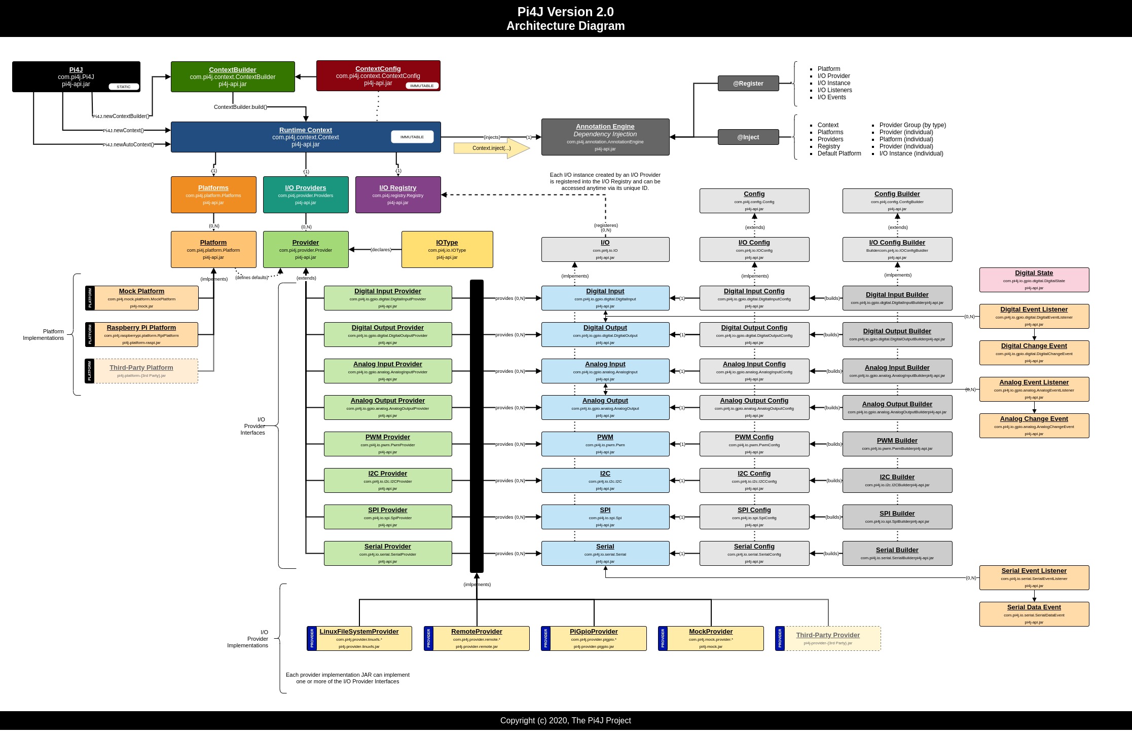
Architecture: See: https://pi4j.com/architecture/

FDelporte commented 2 years ago

Totally right about the provider documentation! So quickly started adding some info...!

@eitch as you have been working on the LinuxFS implementation is this correct? https://pi4j.com/documentation/providers/linuxfs/

Also listed the PiGpio provider names: https://pi4j.com/documentation/providers/pigpio/

eitch commented 2 years ago

@FDelporte right, i implemented the LinuxFS I2C provider. I should have clarified that a bit more, that the LinuxFS is not complete.

savageautomate commented 2 years ago

I think we are still missing PWM, SERIAL, DIGITAL GPIO and SPI. So actually, I think only I2C is currently implemented. I think the Digital Input and Digital Output providers are just stubbed in but no real impl yet.

tatery commented 2 years ago

@savageautomate thanks for hints. However, to use MCP23017 as GPIO provider I need to communicate with it via I2C so my custom provider must depend on pi4j and other providers (gpio - for interrupt handling and i2c - communication). Any ideas on how to get started?

FDelporte commented 2 years ago

@tatery you can use linuxfs provider for I2C and pipgio for others (see https://pi4j.com/documentation/providers/pigpio/)

tatery commented 2 years ago

@FDelporte any idea how to pass I2C and GPIO settings to my custom provider, while I/O "builder" looks like this (please keep in mind that there could be more than one MCP23017 connected to the Raspberry):

var buttonConfig = DigitalInput.newConfigBuilder(pi4j)
      .id("button")
      .name("Press button")
      .address(PIN_BUTTON)
      .pull(PullResistance.PULL_DOWN)
      .debounce(3000L)
      .provider("pigpio-digital-input");

var button = pi4j.create(buttonConfig);
savageautomate commented 2 years ago

@tatery

OK, so I have been looking into this question and this is the first plugin for an external chip on the 2.x architecture and not everything in terms of implementation have been fully worked out. So in an attempt to work thru the issues, I have created a prototype plugin project here.

https://github.com/savageautomate/pi4j-plugin-microchip

All that I have implemented so far is jus the basic boilerplate for getting the plugin defined and input and output providers established.

I decided to create a single plugin under the name "Microchip" where multiple providers for specific expansion chips can be added later. I know there are several similar chips to the MCP23017 in terms of GPIO pins and communication I/O types. So there is probably the potential for quite of bit of reuse for these similar chips.

Here you can find the first example code attempting to try and use this plugin:

https://github.com/savageautomate/pi4j-plugin-microchip/blob/main/src/test/java/com/pi4j/plugin/microchip/mcp23017/provider/gpio/digital/test/MCP23017GpioOutputExample.java

As far as needing to configure the I2C to pass into the provider, that's where I'm stuck and thinking about the best way to implement this concept. Plugins and their providers are loaded at the time the Pi4J context is created and thus there is sort of a chicken and egg problem where we can't pass an I2C instance to the MCP23017 provider until after the context is created and all providers are already loaded. So we need to somehow pass configuration data/objects to the provider after it's loaded in the Pi4J context but before any I/O is attempted to be created by it.

I'm thinking of the possibility of calling into some custom setup(...) or configure(...) type of method on the provider instance prior to attempting to create the GPIO pin instances. This would technically work but I'm trying to think thru some of the ramifications where we want Pi4J I/O instances to be created declaratively via configuration files and/or annotations.

https://github.com/savageautomate/pi4j-plugin-microchip/blob/376d0db3015c1ad80dae3814eea09a0948fe8795/src/test/java/com/pi4j/plugin/microchip/mcp23017/provider/gpio/digital/test/MCP23017GpioOutputExample.java#L45-L50

        // if we don't have an immediate reference to the actual provider,
        // we can obtain it from the Pi4J context using it's ID string
        MCP23017DigitalOutputProvider provider = pi4j.provider(MCP23017DigitalOutputProvider.ID);

        // TODO :: we need to configure the MCP23017 provider with the necessary SPI/I2C config and any other startup configs
        //provider.configure(...);

        // Here we will create I/O interfaces for a (GPIO) digital output
        // pin. We will use the MCP23017 digital output provider
        var ledConfig = DigitalOutput.newConfigBuilder(pi4j)
                .id("led")
                .name("LED Flasher")
                .address(PIN_LED)
                .shutdown(DigitalState.LOW)
                .initial(DigitalState.LOW)
                .provider(MCP23017DigitalOutputProvider.ID);

        // create the LED output GPIO pin instance
        var led = pi4j.create(ledConfig);

So we could start with something like this just to get moving forward and continue considering if this is the best long-term approach. The providers would need to throw some exception if an I/O instance is attempted but the configure(..)/setup(..) was never invoked.

Thoughts?

tatery commented 2 years ago

@savageautomate thanks for the initial version of the plugin - this is a good place to start. I like your idea to use configure(..)/setup(..), however another issue arises here: other plugins can have different configuration requirements. Some extensions will require I2C and GPIO, while others will only require SPI, etc. So it may be difficult to unify configure(..)/setup(..).

You wrote: "Plugins and their providers are loaded at the time the Pi4J context is created and thus there is sort of a chicken and egg problem" so maybe a better option is to have the method to manually register/add custom providers when the pi4j context is ready.

savageautomate commented 2 years ago

@tatery

I'm leaning towards the method name setup(...) implying that some initial action is required to setup the provider as well as it better implies that it may not be reentrant or idempotent. "Configure" suggests that one could call it again to re-configure a provider or modify a provider and that may not be the case (or a supported case) once I/O instances are created.

... so maybe a better option is to have the method to manually register/add custom providers when the pi4j context is ready.

There is a method to manually register providers in the context builder ... but once the context is created nothing more can be modified. I think this guarantees that any consumer of the Pi4J context has a definitive set of providers that can't be added or removed by some other part of the code.

... however another issue arises here: other plugins can have different configuration requirements. Some extensions will require I2C and GPIO, while others will only require SPI, etc. So it may be difficult to unify configure(..)/setup(..).

Yes, they most certainly will have different setup method arguments/requirements for various provider implementations. The setup(...) method would be a custom method defined directly on the custom xxxProvider class thus allowing for custom arguments. The user would have to use the explicit provider interface/class type when attempting to call the setup(...) method. i.e.:

        // if we don't have an immediate reference to the actual provider,
        // we can obtain it from the Pi4J context using it's ID string
        MCP23017DigitalOutputProvider provider = pi4j.provider(MCP23017DigitalOutputProvider.ID);

        // TODO :: we need to configure the MCP23017 provider with the necessary SPI/I2C config and any other startup configs
       provider.setup(mcp23017_i2c_instance);

Pi4J could optionally define an abstract setup method on the Provider interface with a varargs parameter to accept any number of Objects. Implementations of the Provider interface could create overridden setup methods with the specifically typed arguments just as in the example above. But at least this generic setup method may provide some attempt at consistency or standards between providers. This may also help provide a means to better handle some declarative or future annotated means of getting the provider properly configured without explicit code.

public abstract void setup(Object ... args);

Thoughts? Thanks, Robert

savageautomate commented 2 years ago

I went ahead and updated the prototype code to support the setup(...) method concept. Albeit without modifications to Pi4J interfaces at this time. https://github.com/savageautomate/pi4j-plugin-microchip/blob/main/src/test/java/com/pi4j/plugin/microchip/mcp23017/provider/gpio/digital/test/MCP23017GpioOutputExample.java

By the way, here is the original MCP23017 implementation from Pi4J v1 if there is anything of value to lift from there: https://github.com/Pi4J/pi4j-v1/blob/release/1.2/pi4j-gpio-extension/src/main/java/com/pi4j/gpio/extension/mcp/MCP23017GpioProvider.java

Other random thoughts .... this plugin/provider would probably benefit from this incomplete feature as well: https://github.com/Pi4J/pi4j-v2/pull/30

tatery commented 2 years ago

The setup(..) method is alright ;)

savageautomate commented 2 years ago

@tatery

I went ahead and started plugging in some of the implementation code in the prototype project: https://github.com/savageautomate/pi4j-plugin-microchip/commit/32c873de9fb821582bc9908c2c736200394f226c

In theory, you might get Digital outputs working with this code on the MCP23017. Its still incomplete but may be worth a try and test it if you have the hardware setup (I do not at this time).

In this example code you would need to use a real I2C provider. I just stubbed in the Mock provider to play with. https://github.com/savageautomate/pi4j-plugin-microchip/blob/main/src/test/java/com/pi4j/plugin/microchip/mcp23017/provider/gpio/digital/test/MCP23017GpioOutputExample.java

tatery commented 2 years ago

@savageautomate thanks a lot. I have the hardware and I will definitely try it out.

FDelporte commented 2 years ago

Please also take a look at https://github.com/Pi4J/pi4j-device-tca9548/tree/master/src/main/java/com/pi4j/devices/mcp23017 where @taartspi already did a lot of work to create additional providers for Pi4J V2.

savageautomate commented 2 years ago

@tatery

A few more improvements to the prototype code today. It should work for both DIGITAL INPUT and OUTPUT but only when polling input states. The code to handle MCP23017 interrupts and propagate GPIO events for inputs is not implemented yet.

@FDelporte (RE: https://github.com/Pi4J/pi4j-device-tca9548/tree/master/src/main/java/com/pi4j/devices/mcp23017) That code is not really following the "Provider" model. So I don't think its pluggable into the Pi4J framework as a reusable GPIO digital input/output provider. If we can get https://github.com/savageautomate/pi4j-plugin-microchip fully working this could be moved under the Pi4J GitHub umbrella and serve as an example for others.

taartspi commented 2 years ago

@tatery Correct comment the tca9548 stream is a module implementation, but not provider. @savageautomate We never returned to my initial provider code and its implementation questions. I can see this thread has moved past that old discussion, which code stream do I download to participate ?

savageautomate commented 2 years ago

@taartspi

We never returned to my initial provider code and its implementation questions. I can see this thread has moved past that old discussion, which code stream do I download to participate ?

Sorry. I must have dropped the ball on that one.

Let's work from here: https://github.com/savageautomate/pi4j-plugin-microchip and just focus on Microchip devices at this time. Feel free to create issues/questions in that repo as well.

Once we get a fully working plugin defined and work out all the configuration details we can use it as a reference to create other plugins/providers for other chipsets.

Thanks, Robert

taartspi commented 2 years ago

@savageautomate said adding interrupts was work to be done. In using this chip I view it as, I write to the chip, and the chip updates the register I requested and possibly that results in modification of the GPIO out register if so configured changing the pin. If my writes configure a pin to now be input and drive an interrupt under specific conditions that pin is reconfigured as an input. When that input pin's level changes it must inform the chip so the chip can determine if an interrupt condition exists. I see the pins and the 'chip' directly coupled, whether that means the pin instances are contained within the 'chip' instance or that each pin has a reference to its chip and the chip to all its pins is a discussion.

savageautomate commented 2 years ago

@taartspi

Not sure if I fully understand your comment. The interrupt enable flag is currently being set (enabled) for each pin configured as a digital input and disabled if set as an output pin.

The logic currently missing is polling (in a separate thread) for the interrupt signal and determining which potential input pins have changed and creating and raising a pin change event in Pi4J. Basically the logic here:

https://github.com/Pi4J/pi4j-v1/blob/release/1.2/pi4j-gpio-extension/src/main/java/com/pi4j/gpio/extension/mcp/MCP23017GpioProvider.java#L443-L585

taartspi commented 2 years ago

@savageautomate Wish were in the same place with a white board as I am confusing things. Not sure why poll. The application would set the mcp registers via this java code to define which pins are input and these definitions are written to the chip. This includes whether the pins interrupt on input change and the possible comparisons performed within the chip before the chip interrupts. All these registers would have been written to the actual chip. If the conditions were meet the chip would then interrupt (high or low as defined by the registers in the chip) Does this clarify the confusion I created ? Going way back to the discussion we both dropped, I thought of the Config work for the pins simply as a way to capture the details defining the pin and that information was immediately used to write the registers in the actual chip. I think I am confused on what behavior you view contained in the java implementations and what is left to the actual chip to perform. Tom

tatery commented 2 years ago

@savageautomate thanks for the next portion of code. I hope to be able to test it in the next couple days.

tatery commented 2 years ago

@savageautomate @FDelporte I tried to test this GPIO provider but I ended up with a problem with the i2c provider. Could you please have a look at the issue: https://github.com/savageautomate/pi4j-plugin-microchip/issues/1

tatery commented 2 years ago

I have opened discussion related to providers implementation and multi-threading: https://github.com/Pi4J/pi4j-v2/discussions/158

taartspi commented 2 years ago

GIT Hub has not updated this record so I will respond this way. I made these changes to Roberts Oct26 code and the LED functions as expected. Minimal providers are loaded

  ***@***.***:~/Pi4J_V2/Pi4J_V2_Team $ git diff

diff --git a/pom.xml b/pom.xml index 794f5c8..6c8116b 100644 --- a/pom.xml +++ b/pom.xml @@ -58,6 +58,21 @@

${slf4j.version}
         <scope>test</scope>
     </dependency>

On Wed, Nov 3, 2021 at 8:41 AM tatery @.***> wrote:

I have fixed issue with missing provider in the following way:

    var pi4j = Pi4J.newContextBuilder()

            .add(

                MCP23017DigitalInputProvider.newInstance()

            ).autoDetectProviders().build();

So now the providers list looks much better:


PI4J PROVIDERS


PROVIDERS: [24] "I/O Providers"

├─SPI: [3]

│ ├─PROVIDER: "RaspberryPi SPI Provider" {raspberrypi-spi} {com.pi4j.plugin.raspberrypi.provider.spi.RpiSpiProviderImpl}

│ ├─PROVIDER: "PiGpio SPI Provider" {pigpio-spi} {com.pi4j.plugin.pigpio.provider.spi.PiGpioSpiProviderImpl}

│ └─PROVIDER: "Mock SPI Provider" {mock-spi} {com.pi4j.plugin.mock.provider.spi.MockSpiProviderImpl}

├─I2C: [4]

│ ├─PROVIDER: "LinuxFS I2C Provider" {linuxfs-i2c} {com.pi4j.plugin.linuxfs.provider.i2c.LinuxFsI2CProviderImpl}

│ ├─PROVIDER: "PiGpio I2C Provider" {pigpio-i2c} {com.pi4j.plugin.pigpio.provider.i2c.PiGpioI2CProviderImpl}

│ ├─PROVIDER: "RaspberryPi I2C Provider" {raspberrypi-i2c} {com.pi4j.plugin.raspberrypi.provider.i2c.RpiI2CProviderImpl}

│ └─PROVIDER: "Mock I2C Provider" {mock-i2c} {com.pi4j.plugin.mock.provider.i2c.MockI2CProviderImpl}

├─DIGITAL_OUTPUT: [4]

│ ├─PROVIDER: "PiGpio Digital Output (GPIO) Provider" {pigpio-digital-output} {com.pi4j.plugin.pigpio.provider.gpio.digital.PiGpioDigitalOutputProviderImpl}

│ ├─PROVIDER: "Mock Digital Output (GPIO) Provider" {mock-digital-output} {com.pi4j.plugin.mock.provider.gpio.digital.MockDigitalOutputProviderImpl}

│ ├─PROVIDER: "RaspberryPi Digital Output (GPIO) Provider" {raspberrypi-digital-output} {com.pi4j.plugin.raspberrypi.provider.gpio.digital.RpiDigitalOutputProviderImpl}

│ └─PROVIDER: "LinuxFS Digital Output (GPIO) Provider" {linuxfs-digital-output} {com.pi4j.plugin.linuxfs.provider.gpio.digital.LinuxFsDigitalOutputProviderImpl}

├─ANALOG_INPUT: [1]

│ └─PROVIDER: "Mock Analog Input (GPIO) Provider" {mock-analog-input} {com.pi4j.plugin.mock.provider.gpio.analog.MockAnalogInputProviderImpl}

├─DIGITAL_INPUT: [5]

│ ├─PROVIDER: "Mock Digital Input (GPIO) Provider" {mock-digital-input} {com.pi4j.plugin.mock.provider.gpio.digital.MockDigitalInputProviderImpl}

│ ├─PROVIDER: "RaspberryPi Digital Input (GPIO) Provider" {raspberrypi-digital-input} {com.pi4j.plugin.raspberrypi.provider.gpio.digital.RpiDigitalInputProviderImpl}

│ ├─PROVIDER: "LinuxFS Digital Input (GPIO) Provider" {linuxfs-digital-input} {com.pi4j.plugin.linuxfs.provider.gpio.digital.LinuxFsDigitalInputProviderImpl}

│ ├─PROVIDER: "PiGpio Digital Input (GPIO) Provider" {pigpio-digital-input} {com.pi4j.plugin.pigpio.provider.gpio.digital.PiGpioDigitalInputProviderImpl}

│ └─PROVIDER: "MCP23017 Digital Input (GPIO) Provider" {mcp23017-digital-input} {com.pi4j.plugin.microchip.mcp23017.provider.gpio.digital.impl.MCP23017DigitalInputProviderImpl}

├─PWM: [3]

│ ├─PROVIDER: "Mock PWM Provider" {mock-pwm} {com.pi4j.plugin.mock.provider.pwm.MockPwmProviderImpl}

│ ├─PROVIDER: "RaspberryPi PWM Provider" {raspberrypi-pwm} {com.pi4j.plugin.raspberrypi.provider.pwm.RpiPwmProviderImpl}

│ └─PROVIDER: "PiGpio PWM Provider" {pigpio-pwm} {com.pi4j.plugin.pigpio.provider.pwm.PiGpioPwmProviderImpl}

├─SERIAL: [3]

│ ├─PROVIDER: "PiGpio Serial Provider" {pigpio-serial} {com.pi4j.plugin.pigpio.provider.serial.PiGpioSerialProviderImpl}

│ ├─PROVIDER: "Mock Serial Provider" {mock-serial} {com.pi4j.plugin.mock.provider.serial.MockSerialProviderImpl}

│ └─PROVIDER: "RaspberryPi Serial Provider" {raspberrypi-serial} {com.pi4j.plugin.raspberrypi.provider.serial.RpiSerialProviderImpl}

└─ANALOG_OUTPUT: [1]

└─PROVIDER: "Mock Analog Output (GPIO) Provider" {mock-analog-output} {com.pi4j.plugin.mock.provider.gpio.analog.MockAnalogOutputProviderImpl}

— You are receiving this because you were mentioned. Reply to this email directly, view it on GitHub https://github.com/Pi4J/pi4j-v2/issues/138#issuecomment-959105377, or unsubscribe https://github.com/notifications/unsubscribe-auth/AK5A326MSCBWNVGWJZRAMILUKE3XVANCNFSM5GIYK6UQ . Triage notifications on the go with GitHub Mobile for iOS https://apps.apple.com/app/apple-store/id1477376905?ct=notification-email&mt=8&pt=524675 or Android https://play.google.com/store/apps/details?id=com.github.android&referrer=utm_campaign%3Dnotification-email%26utm_medium%3Demail%26utm_source%3Dgithub.

taartspi commented 2 years ago

@savageautomate @tatery I think this example device is near to actual implementation. I have some design questions that once understood, anyone with spare cycles can help code. Tom MCP23017DsnPts.pdf

savageautomate commented 2 years ago

@taartspi

@savageautomate ... Not sure why poll. The application would set the mcp registers via this java code to define which pins are input and these definitions are written to the chip. This includes whether the pins interrupt on input change and the possible comparisons performed within the chip before the chip interrupts. All these registers would have been written to the actual chip. If the conditions were meet the chip would then interrupt (high or low as defined by the registers in the chip) Does this clarify the confusion I created

It's entirely possible that I'm missing something. I'm not an expert with these chips and I'm working from my memory when I first implemented this chip several years ago.

My understanding is that if pins are configured as input pins and the pin interrupts are enabled, then anytime one of those pins states get changed electronically (HIGH -> LOW | LOW <- HIGH) the interrupt registers indicate a notification that the pin states have changed. But we have to poll to read the interrupt states for unsolicited changes ... right?

Thanks, Robert

savageautomate commented 2 years ago

@taartspi

Not sure if I'm going to help clarify or make things worse ... but here goes ....

Device contains pins. The chip contains a list of its pins. Reading the data sheet, details are documented based on the chips registers where user code updates a register and that may update an output pin. The documentation does not imply user code directly access a pin. I think the new example code directly accessing the Pin is not how this should be written. I think the user code should access the chip and the chip access the PIN when required. So rather than pin.high(), chip.pinHigh(pinNumber).

The API in Pi4J surrounds the concept of I/O instances. In the case of basic GPIO, these can potentially be:

So we consider chips like the MCP23017 (a GPIO expander) that augments the RPi on-board GPIO with additional GPIO digital input/output pins. Fundamentally the user should not really care about the "chip" itself other than to establish the proper addressing and communication parameters. Thus we implement this GPIO expander chip as a custom plugin that exports custom Digital Input and Digital Output providers. Users only barely interact with the provider itself. Mainly they just use the provider to create digital input/output pins instances. The Pi4J APIs would not expose any chip APIs to perform chip-wide operations such as RESET chip. The Pi4J provider implementation make make use of the chip registers for configuration and runtime but would not expose any register specifics. I'm not saying that a custom provider can't choose to offer augmented APIs but they would not be required or enforced by the Pi4J API interfaces.

Other pin and device attributes There are attributes specific to IN/OUT pins, and a few specific to the CHIP. Each of the three groups can be implemented following the pattern in the example

Device INIT reads HW Upon initialization the chip could read the existing device register values and populate the pin list with the proper IN or OUT pin. The actual pin code should runtime validate the pin direction is correct, but populating this list means a chip.prettyPrint() method could display the complete details.

Pi4J does not have the concept of instantiating GPIO instances based on previous (underlying) pin configuration or hardware detection. Pi4J expects that the user create the GPIO instance and define any configuration parameters such as PULL UP/DOWN up front. Pi4J provider implementation code would then take the necessary steps to ensure the pin on the hardware is configured properly based on this user defined configuration. (pin direction, pin interrupts, pin pull-resistance, etc.)

Reset Example app Provide separate example app that drives a SOC gpio to reset the chip.

We could optionally expose a custom method from the provider to perform a chip reset; however it's not part of the Pi4J API interfaces. Additionally, this provider will be re-used for multiple I/O instances thus coordinating a reset state across all instances my be necessary. Perhaps there is no need to expose a RESET and avoid these complications. Users can manually define and initialize all the pins which may effectively act like a reset?

Example Interrupt Monitor Supply a separate ‘app’ example that monitors for an input pin configured to interrupt. This should reference the GPINTEN DEFVAL and INTCON pin-IOCON.ODR pin-IOCON.INTPOL pin IOCON.MIRRO only to let the reader know various configuration possibilities exist. A single actual example is all that is needed.

I think an interrupt polling mechanism is needed inside the provider implementation. Pi4J expects to raise DIGITAL STATE change events anytime an input pin or output pin state is changed. Output pin states changes are easy because we control the pin state; however for input pins, these can change state externally so we have to read the chip's registers to know if a change occurred. As far as the specific interrupt register values, and behavior I think that is all internal to the provider's implementation. The provider chooses how best to communicate with the chip and setup interrupts for its own monitoring needs. I don't think any interrupt logic is exposed to the user apart from the standard Pi4J digital state change events.


At the end of the day ... the Pi4J viewpoint is that we are allowing users to use a custom GPIO expander chip and it's associated provider plug-in to offer more GPIO within the Pi4J framework. Pi4J is not attempting to create an API layer for all the various chipsets and is not attempting to expose chipset specifics to the end user. The goal is for users to not have to understand the chipset and it's specific communication and behavior but rather to abstract away all the complexity and just allow users to get on with their GPIO goals :-)

I hope this helps .... Thanks, Robert

tatery commented 2 years ago

My understanding is that if pins are configured as input pins and the pin interrupts are enabled, then anytime one of those pins states get changed electronically (HIGH -> LOW | LOW <- HIGH) the interrupt registers indicate a notification that the pin states have changed. But we have to poll to read the interrupt states for unsolicited changes ... right?

@savageautomate you are right :) I think @taartspi is talking about hardware interrupts handling instead of pooling registers in loops. As you know, the MCP23017 has two ports: A and B. Each port has its own interrupt pin: INTA and INTB. These 2 lines can be used instead of pooling mechanism and read registers when either INTA or INTB has change (BTW I have already prepared "my" version of this provider to use hardware interrupts to know when registers have to be read). @taartspi please correct me if I'm wrong.

savageautomate commented 2 years ago

@tatery

Thanks for pointing this out ... it finally clicked in my head .... You mean potentially physically connecting the interrupt pins (INTA & INTB) to real GPIO pins on the RPi? I guess I have not considered that because of what was implemented in Pi4J V1. If we support this physical connection we could simply listen for standard GPIO interrupts from the RaspberryPi and not need a polling routine/thread. I do like that idea; however not sure if that meets all use cases.

Pi4J v1.x implemented the polling thread to monitor the interrupt registers (INTFA & INTFB). This way it could offer the GPIO events and not require users to tie up additional GPIO pins on the RPI itself.

Some of the original Pi4J implementation code for the MCP chips were related to the PiFace add-on board. See here, the INTA and INTB pins are not connected.

PiFaceDigital

Thoughts?

Thanks, Robert

taartspi commented 2 years ago

@savageautomate @tatery You are correct, I was referring to the chips interrupt lines. Each individual pin can configure several rules whether a pin input change should trigger and interrupt. Normally this mechanism would be used as opposed to an app polling. Robert it is this support where your earlier explanation of your preferred GPIO abstraction differs with my thoughts. under the covers your GPIO description could use this mechanism and then read the INTF reg to know what pin changed and inform any listeners of that pin. I see u made an update, let me jump and read that. Your last entry entry, thoughts ? The chip can be configured to route both banks interrupt to a single line, thus only tie up one Pi gpio. I think the way to go is, either we create a mcp23017 chip containing pins and the app accesses the chip, or we do not use mcp23017 in the pin class name, follow your earlier thought and provide an expansion of the gpios and tell the customer they must attach an mcp23017 to the Pi in order to use the expansion gpios I think either way would be beneficial, if we do the gpio expansion and not the chip, I think we need to do a simple chip like a tempSensor as a complete example of a device.

tatery commented 2 years ago

You mean potentially physically connecting the interrupt pins (INTA & INTB) to real GPIO pins on the RPi

@savageautomate exactly. I have modified your implementation of MCP23017 provider to operate in this way and it is working pretty fine ;) My version is not completed yet but in final release I'd like to have an option to use pooling when INTx pins are not configured.

taartspi commented 2 years ago

Good. I have working listener code in my old example but it sounds like you can write code faster than find/understand my old code.

tatery commented 2 years ago

@savageautomate I configure the MCP23017 provider in the following way:

        I2C mcp23017_i2c = pi4j.i2c().create(MCP23017_I2C_BUS, MCP23017_I2C_ADDRESS);
        MCP23017DigitalInputProvider provider = pi4j.provider(MCP23017DigitalInputProvider.ID);

        var intAConfig = DigitalInput
                .newConfigBuilder(pi4j)
                    .id("intA")
                    .name("test-intA")
                    .address(26)
                    .pull(PullResistance.PULL_UP)
                    .debounce(300L)
                    .provider("pigpio-digital-input");
        var intA = pi4j.create(intAConfig);

        provider.setup(mcp23017_i2c, intA, intA);

When INTA == INTB then both interrupts are handled by the same Raspberry PIN, so MIRROR bit of REGISTER_ICON_A has to be 1 - the INT pins are internally connected When INTA != INTB then interrupts are handled by different Raspberry PINs or only one port has hardware interrupt connected and second port has to be handled using pooling mechanism (MIRROR bit of REGISTER_ICON_A has to be 0). When INTA==null and INTB==null then MIRROR bit of REGISTER_ICON_A has to be 0 and pooling mechanism has to be used for both ports

I hope to push some part of my code as PR in the next week.

taartspi commented 2 years ago

Then wire the mcp interrupt line(s) to Pi gpio(s).
Add a listener on that Pi gpio.
When fired inspect the mcp INTF register to see what pin interrupted. Read INTCAP or GPIO register to clear the interrupt

savageautomate commented 2 years ago

@tatery

Your setup() method is what I was environing as well to support the wired interrupts. Perhaps overloaded methods:

provider.setup(I2C i2c);  <-- NO WIRED INTERRUPTS, USE REGISTER POLLING

provider.setup(I2C i2c, 
               DigitalInput interrupt);  <-- USE SINGLE WIRED INTERRUPT FOR BOTH PORT A & B

provider.setup(I2C i2c, 
               DigitalInput interruptA, 
               DigitalInput interruptB);  <-- USE SEPARATE WIRED INTERRUPTS FOR PORT A & B

I think your interrupt pin comparison and NULL logic would still apply on the third overloaded method above.

Feel free to use a pull request for code changed on the project. I think I sent invitations to you both for any changes to that repo.

savageautomate commented 2 years ago

Then wire the mcp interrupt line(s) to Pi gpio(s). Add a listener on that Pi gpio. When fired inspect the mcp INTF register to see what pin interrupted. Read INTCAP or GPIO register to clear the interrupt

I think we are all on the same page now. And the polling logic could be optional/supplemental and only needed if no physical interrupts pins are assigned.

Thanks, Robert

savageautomate commented 2 years ago

I think we need to do a simple chip like a tempSensor as a complete example of a device.

Unless implemented as an AnalogOutput provider, we really don't have a low-level API to handle things like temperature sensors, accelerometers, lux sensors, etc. So yes, this could be purely example code.

There is a recent discussion about higher level component and devices here: https://github.com/Pi4J/pi4j-v2/discussions/151

I think that does present an interesting challenge/question ... Should there be some generic core API for sensors for provide a variety of data outputs complete with eventing? We would need to devise some form of Sensor (IO object), SensorConfig, and SensorProvider API. I'm just not sure if the concept of Sensors belong in the core PI4J API or some higher level components APIs.

Thanks, Robert

taartspi commented 2 years ago

I understand u not wanting this as part of the core. We can think about how/what we demonstrate a user implementation of a device as a provider. Or if this is even an item we should consider

. And yes. As far as being on the same page i now better understand your gpio expansion requirement. We can limit what mcp23017 details are exposed to the user to ensure we only expose what is similar to the PI gpio pins. Leave other mcp configuration details for our internal implementation needs.

On Thu, Nov 4, 2021 at 11:36 PM Robert Savage @.***> wrote:

I think we need to do a simple chip like a tempSensor as a complete example of a device.

Unless implemented as an AnalogOutput provider, we really don't have a low-level API to handle things like temperature sensors, accelerometers, lux sensors, etc. So yes, this could be purely example code.

There is a recent discussion about higher level component and devices here:

151 https://github.com/Pi4J/pi4j-v2/discussions/151

I think that does present an interesting challenge/question ... Should there be some generic core API for sensors for provide a variety of data outputs complete with eventing? We would need to devise some form of Sensor (IO object), SensorConfig, and SensorProvider API. I'm just not sure if the concept of Sensors belong in the core PI4J API or some higher level components APIs.

Thanks, Robert

— You are receiving this because you were mentioned. Reply to this email directly, view it on GitHub https://github.com/Pi4J/pi4j-v2/issues/138#issuecomment-961622062, or unsubscribe https://github.com/notifications/unsubscribe-auth/AK5A32YP36IPHGYGSLT4OPDUKNUNZANCNFSM5GIYK6UQ . Triage notifications on the go with GitHub Mobile for iOS https://apps.apple.com/app/apple-store/id1477376905?ct=notification-email&mt=8&pt=524675 or Android https://play.google.com/store/apps/details?id=com.github.android&referrer=utm_campaign%3Dnotification-email%26utm_medium%3Demail%26utm_source%3Dgithub.