Open Pottus opened 9 years ago
Kinda lol moment. I'm completely new to the normals and shit, I came up with the following but it doesn't work. I figured it'd be something along those lines.
stock SurfaceNormals(Float:P1[3], Float:P2[3], Float:P3[3], &Float:normX, &Float:normY, &Float:normZ, &Float:vectX, &Float:vectY, &Float:vectZ)
{
//Normal of three points?
normX = (P2[0] - P1[0]) * (P3[0] - P1[0]);
normY = (P2[1] - P1[1]) * (P3[1] - P1[1]);
normZ = (P2[2] - P1[2]) * (P3[2] - P1[2]);
//Make sum of 'vect' come out as 1, it shouldn't be 0.
vectX = normX / (floatabs(normX) + floatabs(normY) + floatabs(normZ));
vectY = normY / (floatabs(normX) + floatabs(normY) + floatabs(normZ));
vectZ = normZ / (floatabs(normX) + floatabs(normY) + floatabs(normZ));
}
stock CA_SurfaceNormals(Float:StartX, Float:StartY, Float:StartZ, Float:EndX, Float:EndY, Float:EndZ, &Float:normX, &Float:normY, &Float:normZ, &Float:vectX, &Float:vectY, &Float:vectZ)
{
new Float:P1[3], Float:P2[3], Float:P3[3];
//floatsin(120, degrees) = 0.86602540378443864676372317075294
//floatcos(120, degrees) = -0.5000000000000000000000000000000
//floattan(120, degrees) = -1.7320508075688772935274463415059
//Get three points on a surface (NOT the best method but yea).
CA_RayCastLine(StartX, StartY, StartZ,
EndX + 0.01, EndY + 0.01, EndZ,
P1[0], P1[1], P1[2]);
CA_RayCastLine(StartX, StartY, StartZ,
EndX, EndY + 0.01, EndZ + 0.01,
P2[0], P2[1], P2[2]);
CA_RayCastLine(StartX, StartY, StartZ,
EndX + 0.01, EndY, EndZ + 0.01,
P3[0], P3[1], P3[2]);
SurfaceNormals(P1, P2, P3, normX, normY, normZ, vectX, vectY, vectZ);
}
The vectors of the CA func always come out to one of the following (it seems):
0, 0, 0
0, 1, 0
0, 0, 1
It is kind of confusing not to say the least.
normX = (P2[0] - P1[0]) * (P3[0] - P1[0]); normY = (P2[1] - P1[1]) * (P3[1] - P1[1]); normZ = (P2[2] - P1[2]) * (P3[2] - P1[2]); Is in short: N = (P2-P1)*(P3-P1)
Then for the vectors I'm sure I have it incorrect. Is should be something like: n^=1v/n OR Vx=Nx/(|Nx|+|Ny|+|Nz|) Vy=Ny/(|Nx|+|Ny|+|Nz|) Vz=Nz/(|Nx|+|Ny|+|Nz|)
@Crayder your algorithm is valid for tri-meshes, if you are ray tracing at three different points to get a triangle, you are doing it absolutely wrong. What if the object is a sphere or a hull shape or the traced ray is tangent to the surface ? and your triangle can consist of various other tri-meshes which is totally in accurate.
Getting the normal can be very complicated. Steps:
• Get the face where the ray has hit
• Get the vertices of it.
• calculate the normal using your algorithm.
The main complication here, is getting the hit face and it's vertices.
Did you google it ? (your method)
If you did, that site might contain information about triangles, which you passed out.
I think there is a way to do it in bullet.
if(rayCall.hasHit())
{
btVector3 normal = rayCall.m_hitNormalWorld;
}
Tell me whether it works or not.
Did you google it ? (your method)
If you did, that site might contain information about triangles, which you passed out.
Well I googled the small things above; I translated it to x, y, and z.
@Pottus Are you looking for something like this:
If I got it wrong, then please correct me.
Yes, that's what he needs.
Okay, so if you want to calculate the angle which is made by the ray and the normal. You have to do this, I guess.
if(rayCall.hasHit())
{
btVector3 normal = rayCall.m_hitNormalWorld.angle(vector); //start or end vector of the ray
}
Yes picture those lines as objects, I am looking for the correct rotation so that the object would be aligned on the surface perfectly.
I will check you pull requests Saturday thanks, I am away for two days.
Okay, now I get you. I am finding a way for it, looks very difficult though.
Yes, do look at the pull request. I have closed two of them because I did some mistake there. Although, there is one open clean request.
EDIT: I think it can only be done with objects consisting of meshes because you cannot have a vertex on a spherical child shape.
What do you mean by "spherical child shape"?
I'm pretty sure every object has a triangular mesh, even spheres. Look at JernejL's collision mesh (wireframe) layer in Map Construction, it has triangles for every object's collision. These triangle faces are all you would need to do this. Is it possible to get the three points of the face collided in bullet?
For example, these two objects:
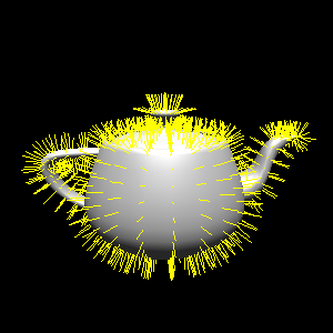
Their mesh looks like this:
We just need a way to detect the exact face collided and take it's three points (or three points on the face), calculate the normal vectors, convert to angles.
On a side note, has Chris made any progress with loading SA-MP objects? Mumble has been quite the past few days.
All samp objects consist of meshes but not all gta objects contains meshes, I guess. Try to check the wireframe of id 2114 I think it is ball.
Object 2114 does have a mesh, without a mesh there would be no shape or anything to apply texture to; but, it doesn't have a collision, and without a collision you can't collide with it in GTA, SA-MP, or CA.
There are however three basketball objects. 1946, 2114, and 3065. The first two do not have collisions, the last one does. Here are all three, listed from least to greatest:
Here are their collisions:
And finally, the wireframes:
As you can see, the only basketball that would work from your defensive example is 3065, the only one with a collision (and therefore, a tri-mesh).
Yes, I think renderware consider spherical objects as a polyhedral shape. I am not sure about bullet's consideration. Okay, test it with object, 2887, 19789, 2896, 2942. They don't have meshes at all and they are quite inaccurate in terms of their shape, especially object 2942.
Yes, I think renderware consider spherical objects as a polyhedral shape. I am not sure about bullet's consideration.
The objects have multiple meshes (i.e. collision mesh, and the other one). Also, spheres are not spheres in terms of gta objects.
Okay, test it with object, 2887, 19789, 2896, 2942. They don't have meshes at all and they are quite inaccurate in terms of their shape, especially object 2942.
Those also have meshes. They are just a few of the exceptional ones that do not have a good collision mesh. SInce their collision mesh is so simplified you could just take three corners and work like a trimesh. You can use any three on the same face, they will all give the same vectors.
The objects have multiple meshes (i.e. collision mesh, and the other one)
What's "the other one" ? EDIT: A single object cannot posses multiple meshes. (either collision mesh or no-collision mesh)
Also, spheres are not spheres in terms of gta objects.
That's what I said, they are polyhedral.
Those also have meshes. They are just a few of the exceptional ones that do not have a good collision mesh.
No, they do not have collision trimeshes. They only consist of texture mapping meshes, textures and collision volumes.
SInce their collision mesh is so simplified you could just take three corners and work like a trimesh. You can use any three on the same face, they will all give the same vectors.
Well, how will you determine their face ? GTA SA does not provide vertices for collision volumes, just only for meshes.
If that's your argument, then mine is how will you determine the vertices on the trimesh? Apparently it's being done already or we wouldn't have the RayCastLineAngle function.
What's "the other one" ?
EDIT: A single object cannot posses multiple meshes. (either collision mesh or no-collision mesh)
Obviously they can, you even said so just after you said this:
They only consist of texture mapping meshes, textures and collision volumes.
Exactly. They have both a collision mesh and a texture mesh. Here is my favorite example (other than the 3065's collision vs texture mesh):
Obviously, the texture mesh is not the same as the collision mesh. The collision mesh is what ColAndreas detects. On this silo object RayCastLineAngle actually returns perfect values, just noting.
We can determine the vertices of trimesh, they are actualy provided in .col files. I've answered your "argumentative" question. Now, you answer mine.
For the silos, it clearly shows that they only consist of texture mapping meshes and collision volumes. If it had collision mesh then it should have a convex hull mesh on the top of it.
We can determine the vertices of trimesh, they are actualy provided in .col files. I've answered your "argumentative" question. Now, you answer mine.
I think you just answered it yourself, no need. If those are provided there must be a way to get the vertices of the quad meshes like that the silos have. Like I said before, the silos return perfect angles, and they do not have a trimesh.
For the silos, it clearly shows that they only consist of texture mapping meshes and collision volumes. If it had collision mesh then it should have a convex hull mesh on the top of it.
The outer box is the collision. So aren't we both correct there?
We shall not say it as a quad mesh (or poly mesh) because old games contains only trimesh. The silos only have a texture mesh and a collision volume. Collision files does not provide vertices for collision volumes and never will, because we actually do not need it and I did not answer myself, I guess. What angles are you talking about ?
The outer box is the collision. So aren't we both correct there?
Kinda, you said it's a mesh and I said, it is a collision volume. mesh =/= collision volume
mesh =/= collision volume
true
What angles are you talking about ?
The angles returned by RayCastLineAngle, obviously... :P
// Instead of returning the position of collision this will return the rx / ry rotation of the slope (I could use use someone to check over the math here)
native CA_RayCastLineAngle(Float:StartX, Float:StartY, Float:StartZ, Float:EndX, Float:EndY, Float:EndZ, &Float:x, &Float:y, &Float:z, &Float:rx, &Float:ry);
Yea, it returns the slope so it will be accurate. According to me slope is: theta = tan^-1(StartY-y/StartX-x)
The point of this issue is finding a way to get the 'slope' of all surfaces in the collision. That's why we need three points and a normal. Go to the performRayTestAngle function in DynamicWorld.cpp to see where the current math is. It's only X and Y, but it works in most cases (like the silos for example XD). There are a few surfaces it doesn't work for such as the sides of some buildings, fences, some ground, and other objects.
Yea, I understood now what he meant by slope.
@Pottus is this what you wanted ?
btVector3 hit = rayCall.m_hitPointWorld;
btVector3 normal = rayCall.m_hitNormalWorld;
float angle = hit.angle(normal);
float rX = (hit.getX() * cos(angle)) - (hit.getY() * sin(angle));
float rY = (hit.getY() * cos(angle)) + (hit.getX() * sin(angle));
Oh wait, you need the angles.
EDIT: I think rotations need in depth Quaternions and I have no idea about it. But, if you want something like this without user oriented data.
I can try.
Basically what we need to do is find the rotation needed to make an object parallel to a surface given the surface's normal.
What we really need is a version of Unity's Quaternion.FromToRotation
That Unity function aligns an axis of an object with a surface normal. This is exactly what we need to do. So, does anyone have the source code of that function? :3
https://github.com/libgdx/libgdx/blob/master/gdx/src/com/badlogic/gdx/math/Quaternion.java
Contains Quaternion functions. I tried decompiling unity, but all Quaternion functions are implemented in C++, and I can't decompile that.
The closest thing I found to FromToRotation
there was getAxisAngle
, I don't think it's what we need.
@Pottus
Perhaps this (4th post) is what we need?
http://www.bulletphysics.org/Bullet/phpBB3/viewtopic.php?f=9&t=10790
If not maybe you could post there and provide a better explanation.
rx = acos(nz);
ry = 0.0;
rz = atan2(ny, nx) + 90.0;
I think this is more accurate than the rx/ry version.
nx, ny, nz: Normal Vector rx, ry, rz: Return Rotations
Also, the new mesh fix added in 3c5cfc478f06c7d2991d3aa4b6fc2db2b4d5104b seemed to fix the old normal vector bugs (the one that would cause rotations to be off by a few degrees).
I don't think that will work right to be honest currently it works when placing objects on the ground.
It works perfectly, I've tested it a lot and can provide you results.
Here are just a few, taken in multiple directions.
X = 2322.2290, Y = 1254.1141, Z = 58.1086
nX = 0.0000, nY = -0.7936, nZ = 0.6084
rX = 52.5243, rY = 0.0000, rZ = 0.0000
X = 2353.2312, Y = 1283.3153, Z = 57.5664
nX = 0.7936, nY = 0.0000, nZ = 0.6084
rX = 52.5243, rY = 0.0000, rZ = 90.0000
X = 2275.1169, Y = 1600.4102, Z = 99.8516
nX = -0.0003, nY = -0.5418, nZ = 0.8404
rX = 32.8121, rY = 0.0000, rZ = -0.0343
X = 2275.1169, Y = 1600.4219, Z = 99.8591
nX = -0.0003, nY = -0.5418, nZ = 0.8404
rX = 32.8121, rY = 0.0000, rZ = -0.034
X = 2272.6640, Y = 1625.3664, Z = 82.7343
nX = -1.0000, nY = 0.0000, nZ = 0.0000
rX = 89.9999, rY = 0.0000, rZ = 270.0000
X = 2274.1557, Y = 1634.8671, Z = 82.7343
nX = 0.0000, nY = -1.0000, nZ = 0.0000
rX = 89.9999, rY = 0.0000, rZ = 0.0000
Here is the code I used to ensure the algorithm worked.
GetNormalRot(Float:tx, Float:ty, Float:tz, &Float:rx, &Float:rz) {
rx = acos(tz);
rz = atan2(ty, tx) + 90.0;
}
main() {
CA_Init();
new Vector(X, Y, Z), Vector(nX, nY, nZ), Vector(rX, rY, rZ);
CA_RayCastLineNormal(2270.1558, 1625.3665, 82.7344, 2274.1558, 1625.3665, 82.7344, X, Y, Z, nX, nY, nZ);
GetNormalRot(nX, nY, nZ, rX, rZ);
printf("X = %4.4f, Y = %4.4f, Z = %4.4f\nnX = %4.4f, nY = %4.4f, nZ = %4.4f\nrX = %4.4f, rY = %4.4f, rZ = %4.4f", X, Y, Z, nX, nY, nZ, rX, rY, rZ);
CA_RayCastLineNormal(2274.1558, 1625.3665, 82.7344, 2274.1558, 1635.3665, 82.7344, X, Y, Z, nX, nY, nZ);
GetNormalRot(nX, nY, nZ, rX, rZ);
printf("X = %4.4f, Y = %4.4f, Z = %4.4f\nnX = %4.4f, nY = %4.4f, nZ = %4.4f\nrX = %4.4f, rY = %4.4f, rZ = %4.4f", X, Y, Z, nX, nY, nZ, rX, rY, rZ);
}
Lets see
See as in you're going to test it or as in you want to see pictures, or what? XD
Pictures lol
K, a sec
I layed a line of concrete cubes on the hanger, is this good enough? XD
I think I like the rX/rY angle version better still. With the rX/rZ version rotating on the z axis afterwards fucks things up.
The fix still stands however, I haven't received any odd rotations yet.
Sounds good.
Will this be more accurate?
rx = acos(nx) * RADIAN_TO_DEGREE; //nx normal x of the hit point
ry = asin(ny) * RADIAN_TO_DEGREE; //ny normal y of the hit point
rz = 0.0;
This function needs to be updated to return the correct rx/ry/rz angles for in game objects. I've tried a lot of different things but I am still unsure how to accurately translate the normal to an object rotation in that the object would align perpendicular to the orientation of the collision plane.
I am hoping some math guys out there could figure out the steps to do this correctly it is very important for advanced mapping features.