Closed MarcelloCa closed 5 years ago
There are two issues here:
You have commented out the measurement and conditional corrections on the ancilla qubits needed for teleportation. Without these the output state of the teleported qubit is effectively random.
The process tomography function cannot really handle a teleportation circuit as the function assumes you are preparing and measuring the same qubits. In tomography of a teleportation circuit your input states would be on qubit-0, and your final measurements would be on qubit-2. Where as the process tomography function is applying both the different input states and measurements to qubit-2, which is one of the teleportation ancilla that should be always prepared in 0.
Chriseclectic, thanks for replying.
Indeed, this is confirmed by state tomography. Please see the code below, which performs state tomography by comparing the teleported state at qubit [2] for different setting of qubit [0] (x, h, or arbitrary u3)
import numpy as np
import time
# importing Qiskit
from qiskit import Aer, IBMQ
from qiskit import QuantumRegister, ClassicalRegister, QuantumCircuit
from qiskit import register, execute
# import backend utilities
from qiskit.backends import JobStatus
# import tomography library
import qiskit.tools.qcvv.tomography as tomo
# useful additional packages
from qiskit.tools.visualization import plot_state
from qiskit.tools.qi.qi import *
from qiskit.wrapper.jupyter import *
#from qiskit.backends.ibmq import least_busy
# Load saved IBMQ accounts
#IBMQ.load_accounts()
# Creating registers
q = QuantumRegister(3)
c = ClassicalRegister(3)
qc = QuantumCircuit(q, c, name='teleportation')
# inizializing qubit ⓪ to be teleported
#qc.u1(0.5, q[0])
#qc.x(q[0])
#qc.h(q[0])
qc.u3(0.5, 0.5, 0.5, q[0])
qc.barrier(q)
# creating entangled pair between qubit ① and qubit ②
qc.h(q[1])
qc.cx(q[1], q[2])
qc.barrier(q)
# teleportation
qc.cx(q[0], q[1])
qc.barrier(q)
# Measure qubit ⓪ in the + - basis
qc.h(q[0])
qc.cz(q[0],q[2])
## If needed Perform a phase correction to qubit ③
#qc.measure(q[0], c[0])
#if c[0] == 1:
# qc.z(q[2])
qc.barrier(q)
# Measure qubit ① in the computational basis
qc.cx(q[1],q[2])
## If needed Perform a bit flip correction to qubit ②
#qc.measure(q[1], c[1])
#if c[1] == 1:
# qc.x(q[2])
qc.barrier(q)
# Construct state tomography set for measurement of qubits [0, 1] in the Pauli basis
tomo_set = tomo.state_tomography_set([2])
# Add the state tomography measurement circuits to the Quantum Program
tomo_circuits = tomo.create_tomography_circuits(qc, q, c, tomo_set)
backend = Aer.get_backend('qasm_simulator')
shots = 1000
tomo_job = execute(tomo_circuits, backend=backend, shots=shots)
tomo_results = tomo_job.result()
tomo_data = tomo.tomography_data(tomo_results, 'teleportation', tomo_set)
rho_fit = tomo.fit_tomography_data(tomo_data)
# plot the state
plot_state(rho_fit,'paulivec')
backend = Aer.get_backend('statevector_simulator')
# Creating registers
q = QuantumRegister(1)
c = ClassicalRegister(1)
qc = QuantumCircuit(q, c, name='teleportation')
# inizializing qubit ⓪ to be teleported
#qc.u1(0.5, q[0])
#qc.x(q[0])
#qc.h(q[0])
qc.u3(0.5, 0.5, 0.5, q[0])
job = execute(qc, backend=backend)
psi = job.result().get_statevector(qc)
# construct the density matrix from the state vector
rho = outer(psi)
# plot the state
plot_state(rho,'paulivec')
This is the ideal density matrix of u3(0.5,0.5,0.5) applied to state |0>
And this is the density matrix as output of the state tomography for qubit [2] (Bob's side) with qubit [0] (Alice's side) initialized to u3(0.5,0.5,0.5) as well
Thanks!
Ah ok, I didn't pay enough attention to your circuit. Yes if you do the controlled gates then my first point doesn't matter. State tomography works because you are performing measurements on qubit-2 for an input prepared on qubit-0. Process tomography doesn't work for the reasons I said above: the function is returning circuits that prepare the different tomographic input states on qubit-2, and tomographic measurement on qubit-2. You need the input states prepared on qubit-0, not qubit-2, and measurements on qubit-2.
Any hint or suggestion on how to do it will be greatly appreciated.
There isn't an easy way to do this at the moment. You would have to edit the tomography functions to specify lists of input and output qubits separately.
Chriseclectic, I believe you mean something like this:
{'qubits': [2], 'circuits': [{'prep': {0: ('S', 0)}, 'meas': {2: 'X'}}, {'prep': {0: ('S', 0)}, 'meas': {2: 'Y'}}, {'prep': {0: ('S', 0)}, 'meas': {2: 'Z'}}, {'prep': {0: ('S', 1)}, 'meas': {2: 'X'}}, {'prep': {0: ('S', 1)}, 'meas': {2: 'Y'}}, {'prep': {0: ('S', 1)}, 'meas': {2: 'Z'}}, {'prep': {0: ('S', 2)}, 'meas': {2: 'X'}}, {'prep': {0: ('S', 2)}, 'meas': {2: 'Y'}}, {'prep': {0: ('S', 2)}, 'meas': {2: 'Z'}}, {'prep': {0: ('S', 3)}, 'meas': {2: 'X'}}, {'prep': {0: ('S', 3)}, 'meas': {2: 'Y'}}, {'prep': {0: ('S', 3)}, 'meas': {2: 'Z'}}], 'circuit_labels': ['_prep_S0(0)_meas_X(2)', '_prep_S0(0)_meas_Y(2)', '_prep_S0(0)_meas_Z(2)', '_prep_S1(0)_meas_X(2)', '_prep_S1(0)_meas_Y(2)', '_prep_S1(0)_meas_Z(2)', '_prep_S2(0)_meas_X(2)', '_prep_S2(0)_meas_Y(2)', '_prep_S2(0)_meas_Z(2)', '_prep_S3(0)_meas_X(2)', '_prep_S3(0)_meas_Y(2)', '_prep_S3(0)_meas_Z(2)'], 'prep_basis': {'S': [array([[1, 0],
[0, 0]]), array([[0.33333333, 0.47140452],
[0.47140452, 0.66666667]]), array([[ 0.33333333+0.j , -0.23570226+0.40824829j],
[-0.23570226-0.40824829j, 0.66666667+0.j ]]), array([[ 0.33333333+0.j , -0.23570226-0.40824829j],
[-0.23570226+0.40824829j, 0.66666667+0.j ]])]}, 'meas_basis': {'X': [array([[0.5, 0.5],
[0.5, 0.5]]), array([[ 0.5, -0.5],
[-0.5, 0.5]])], 'Y': [array([[ 0.5+0.j , -0. -0.5j],
[ 0. +0.5j, 0.5+0.j ]]), array([[ 0.5+0.j , 0. +0.5j],
[-0. -0.5j, 0.5+0.j ]])], 'Z': [array([[1, 0],
[0, 0]]), array([[0, 0],
[0, 1]])]}}
It seems working just fine, if needed by someone I can share the code (a couple of lines in process_tomography_set)
Hi @MarcelloCa I put in a patch with this fix in #1454, can you have a look and see if that works for you?
Informations
What is the current behavior?
The process tomography for a teleported state seems providing awkward results. Conversely, state tomography for the same circuit works just fine
Specifically, this is the ideal Chi matrix for a X Gate.
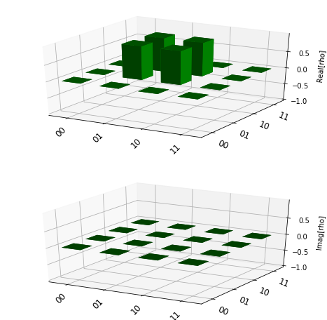
And this is the Chi matrix as output of process tomography
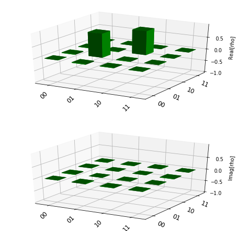
Steps to reproduce the problem
code.txt
What is the expected behavior?
returning a Chi matrix equal or close to id_choi
Suggested solutions