 Tommyboi2001
commented
1 year ago
Tommyboi2001
commented
1 year ago
Open Tommyboi2001 opened 1 year ago
Tommyboi2001
commented
1 year ago
 pacraf
commented
11 months ago
pacraf
commented
11 months ago Until now I disconnected ID2,3 (and both are gen 2_10) ID 0,1 are both hardware 2_0 version
pacraf
commented
11 months ago or easier change order in Arduino , not 0,1,2,3 but 3,2,1,0 , and see if now 0and 1 will start "dominate"
 RoboDurden
commented
11 months ago
RoboDurden
commented
11 months ago Are all four boards running on the same battery ? Do you have an additional GND line from ESP32 to battery ? Better only have one gnd line which you will never detach and only the tx/rx lines to the four boards..
pacraf
commented
11 months ago all on one power supply. lolin is connected to each drive RX,TX,GND
pacraf
commented
11 months ago Maybe I will do differently. I will reprogram let's say swap of ID0 with ID2 ? if nothing will change , that means hardware is not a problem, right?
RoboDurden
commented
11 months ago Until now I disconnected ID2,3 (and both are gen 2_10) ID 0,1 are both hardware 2_0 version
I think best theory for now is that 2.10 is dominate and will supress all serial data that 2.0 is putting on the ESP32-rx line. So when id2 and 3 are disconnected, the 2.0 gets through.
RoboDurden
commented
11 months ago Yes, put id 2,3 on 2_0 and 0,1 on 2_10.
pacraf
commented
11 months ago maybe for now mix them. 0 with 2 . ok? ID 0 = 2.10 slave ID 1 = 2.0 slave ID 2 = 2.0master ID3 = 2.10master if problem stays the same , means hardware is out of scope.
RoboDurden
commented
11 months ago mixing is more complex then swapping.. but i will be happy to watch your complete lolin log output.
pacraf
commented
11 months ago So , I did as I said. now we have ID 0 = 2.10 slave ID 1 = 2.0 slave ID 2 = 2.0master ID3 = 2.10master
and output with all of them connected (and rotating accordingly)
time: 16554 HoverSend to: 0
 CD AB :-)
time: 16566 rx left: 0  iSlave: 0   iOdom: 94       iSpeed: 0.00        iAmp: 0.00      iVolt: 35.33
time: 17554 HoverSend to: 1
time: 18554 HoverSend to: 2
time: 19554 HoverSend to: 3
 CD AB :-)
time: 19566 rx left: 0  iSlave: 3   iOdom: 64       iSpeed: 0.00        iAmp: 0.16      iVolt: 31.12
time: 20554 HoverSend to: 0
 CD AB :-)
time: 20566 rx left: 0  iSlave: 0   iOdom: 126      iSpeed: 0.00        iAmp: 0.00      iVolt: 35.40
time: 21554 HoverSend to: 1
time: 22554 HoverSend to: 2
time: 23554 HoverSend to: 3
 CD AB :-)
time: 23566 rx left: 0  iSlave: 3   iOdom: 64       iSpeed: 0.00        iAmp: 0.12      iVolt: 31.13
time: 24554 HoverSend to: 0
 CD AB :-)
time: 24566 rx left: 0  iSlave: 0   iOdom: 126      iSpeed: 0.00        iAmp: 0.00      iVolt: 35.76
time: 25554 HoverSend to: 1
time: 26554 HoverSend to: 2
time: 27554 HoverSend to: 3
 CD AB :-)
time: 27566 rx left: 0 iSlave: 3 iOdom: 96 iSpeed: 0.00 iAmp: 0.28 iVolt: 31.12so 2_10 can answer, 2_0 not.... hardware related
RoboDurden
commented
11 months ago And when you have pulled 0 and 3 (the two 2.10), then the 2.0 boards reach the Lolin ? This confirms that the 2.10 for some reason is suppressing the 2.0.
pacraf
commented
11 months ago yes, physically removed cables from both 2_10 , makes messages from 2_0 visible
CD AB :-)
time: 62563 rx left: 0  iSlave: 2   iOdom: 913      iSpeed: 0.00        iAmp: 0.20      iVolt: 29.16
time: 63551 HoverSend to: 3
time: 64551 HoverSend to: 0
time: 65551 HoverSend to: 1
 CD AB :-)
time: 65563 rx left: 0  iSlave: 1   iOdom: 772      iSpeed: 0.00        iAmp: 0.20      iVolt: 29.17
time: 66551 HoverSend to: 2
 CD AB :-)
time: 66563 rx left: 0  iSlave: 2   iOdom: 859      iSpeed: 0.00        iAmp: 0.00      iVolt: 29.16
time: 67551 HoverSend to: 3
time: 68551 HoverSend to: 0
time: 69551 HoverSend to: 1
 CD AB :-)
time: 69563 rx left: 0  iSlave: 1   iOdom: 708      iSpeed: 0.00        iAmp: 0.00      iVolt: 29.17
time: 70551 HoverSend to: 2
 CD AB :-)
time: 70563 rx left: 0 iSlave: 2 iOdom: 958 iSpeed: 0.00 iAmp: 0.00 iVolt: 29.16If you have a pocked DSO (osciloscope), you could disconnect a 2.10 and a 2.0 and watch how the hoverboard tx line really looks. It should be 3.3 V with short burst of bits being pulldown to 0 V. Maybe there is a visible difference between 2.10 and 2.0.
You could also monitor the esp rx line with all four boards connected and see the short burst every 1000 ms.
I still have no idea how 2.10 can suppress 2.0.
RoboDurden
commented
11 months ago If you do not have a dso, i think you could put a little led into the rx line: Lolin --->|---- hover. Then you should see the short bursts.
pacraf
commented
11 months ago No DSO. with led I can try. But maybe because on bad luck you selected unlucky pin to TX on 2_10... maybe it is somehow pulled stronger. is it possible to use for TX for example PB4 ?
RoboDurden
commented
11 months ago No you need some new led ----|>|---- which you connect to the esp32 rx pin and then all hover tx lines to the led pin that has the shorter pin.
Anode to ESP32, Kathode to Hover tx lines.
But it might not work anyway. USART0 TX can only be PB6 or PA2 or PA9 or PA14 But you could try the masterSerial uart1 port. You would need to change defines_2-10.h to
// GD32F130 USART0 TX/RX:   (PA9/PA10)AF1   , (PB6/PB7)AF0 ,    (PA2/PA3)AF1 , (PA14/PA15)AF1 GD32F130x4 only!
#define HAS_USART0  // uncomment if this layout has a usart0
#ifdef HAS_USART0
    #define USART0_TX   PB6 // thanks to pacraf
    #define USART0_RX   PB7 // thanks to pacraf

    #define USART0_MASTERSLAVE      // uncomment if this usart is used for master-slave communication
    //#define USART0_REMOTE                     // uncomment if this usart is used for optional remote control
#endif

// GD32F130 USART1 GD32F130 TX/RX: (PA14/PA15)AF1 , (PA2,PA3)AF1    , (PA8/PB0)AlternateFunction4
#define HAS_USART1  // uncomment if this layout has a usart1
#ifdef HAS_USART1
    #define USART1_TX       PA2 // thanks to pacraf
    #define USART1_RX       PA3 // thanks to pacraf

    //#define USART1_MASTERSLAVE        // uncomment if this usart is used for master-slave communication
    #define USART1_REMOTE               // uncomment if this usart is used for optional remote control
#endif
Beware that there is a spelling bug currently in the USART1 section:
    #define USART1_MASTERSLAVE      // uncomment if this usart is used for master-slave communication
    //#define USART0_REMOTE             // uncomment if this usart is used for optional remote control
#endif
It of course must be
    #define USART1_MASTERSLAVE      // uncomment if this usart is used for master-slave communication
    //#define USART1_REMOTE             // uncomment if this usart is used for optional remote control
#endif
But i fear that usart1 and usart0 work alike for the 2.10 or the 2.0, so 2.10 will again kill the 2.0 output.
pacraf
commented
11 months ago you mean like here ?
RoboDurden
commented
11 months ago Yes, bits are transmitted from hover to esp by pulling the data line to gnd. There is a pullup resistor in the ESP32. If it is less then 10k, then a current of 0,33 mA flows. A low-current led should still shine.
pacraf
commented
11 months ago glow barely , no real light , no communication when led is in.
RoboDurden
commented
11 months ago a pocekt dso is a nice thing. Check the delivery time of these offers. If it is 5 days or less then it might be shipping from Poland:
https://www.aliexpress.com/item/1005005644784105.html https://www.aliexpress.com/item/1005005704582390.html https://www.aliexpress.com/item/1005005771384739.html
Oh finally a two channel oscilloscope below 40€: https://www.aliexpress.com/item/1005006019697163.html
pacraf
commented
11 months ago I will think on that, maybe have something at work in workshop. but what this can change. we will OBSERVe the problem, but it seems to be confirmed this will be suppressed line by 2_10. DSO will not change that.. or you are not sure still what is going on? I would rather locate pullups on 2_10 and remove them...
pacraf
commented
11 months ago these pullups are physical resistor or internal pullup in GD? will look on that...
RoboDurden
commented
11 months ago Yes, it also came to me just now, that you could put a 10k resistor in the tx lines from 2.10.
pacraf
commented
11 months ago will try that tommorow. good night !
RoboDurden
commented
11 months ago The idea is like yours: the pullups of 2.10 are to small and therefore the tx line can not be pulled to gnd by the 2.0 boards. With the resistor, this pullups get weakened. The two resistors should not be too big because then the 2.10 might no longer be able to pull the tx line go gnd (which represents a bit transfered).
one resistor might also work:
Good night to Poland :-) You are 1 hour ahead into the night.
RoboDurden
commented
11 months ago Better take a 100k potentiometer so you can test a resistance from 1k - 100k :-)
RoboDurden
commented
11 months ago Yes the pullup resistors on the hover.tx lines seem to be the problem.
2.0 has resistors between the mcu and the uart header:
2.10 may have no resistors in the line but direct connection from mcu to uart header:
My 2.13 has no restistors in the line for sure:
The inline resistors of the 2.0 boards from a voltage divider with the many pullup-resistors :-( Therefore the 2.0 tx output can not pull the esp.rx down to gnd anymore :-(
I tried to disable the mcu internal pullup but unfortunately it did have no effect:
void USART0_Init(uint32_t iBaud)
{
#ifdef HAS_USART0

    // Init USART0
    #if defined(USART0_REMOTE) && defined(REMOTE_UARTBUS)   // no pullup resistors with multiple boards on the UartBus - Esp32/Arduino (Serial.begin) have to setup pullups
        #define USART0_PUPD GPIO_PUPD_NONE
    #else
        #define USART0_PUPD GPIO_PUPD_PULLUP
    #endif
    pinModeAF(USART0_TX, AF_USART0_TX, USART0_PUPD,GPIO_OSPEED_50MHZ);  // // GD32F130: GPIO_AF_0 = USART, GPIO_AF_1 = I2C
    pinModeAF(USART0_RX, AF_USART0_RX, USART0_PUPD,GPIO_OSPEED_50MHZ);
@pacraf , you can add this change to your setup.c file and see if it helps. But i did not see a change with my two 2.13 boards.
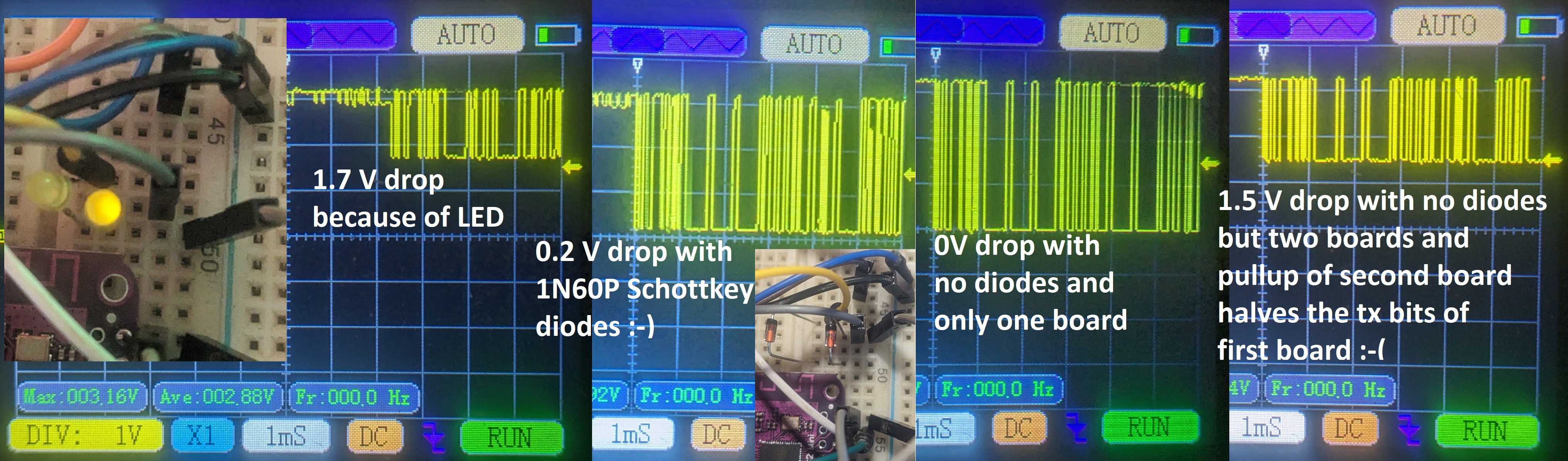
Two 3mm yellow led did prevent the non sending board to pullup the sending board so badly that ESP32 would not detect the bytes. But the yelllow leds did also add a voltage drop of 1.7V. Still the ESP32 did read the 1.7V as zero and the communication worked with two boards connected (a 3mm green led did not work).
So i replaced the yellow led with little Schottky diodes and these only produced a voltage drop of about 0.2 V :-)
I now think, the UartBus needs Schottky diodes like the 1N60P https://www.aliexpress.com/item/1005004104012198.html
RoboDurden
commented
11 months ago @pacraf , if you want to build a huge 4wheeler lawn mover i would suggest an ESP32-CAM https://www.aliexpress.com/item/4000844206042.html (Color: CAM-MB With Antenna) https://lastminuteengineers.com/getting-started-with-esp32-cam/
You could easily (i think) add hoverboard speed/steer levers to

 ncmreynolds
commented
11 months ago
ncmreynolds
commented
11 months ago As an aside, I used a drone FPV camera+TX & goggles on my outdoor rover when testing. This was really nice because it was 100% 'out of band' with anything else to do with the rest of it and did one job. It's more expensive than an ESP32-CAM, which I've also used, but far less flaky/laggy.
On Fri, 3 Nov 2023 at 10:08, Robo Durden @.***> wrote:
@pacraf https://github.com/pacraf , if you want to build a huge 4wheeler lawn mover i would suggest an ESP32-CAM https://www.aliexpress.com/item/4000844206042.html (Color: CAM-MB With Antenna) https://lastminuteengineers.com/getting-started-with-esp32-cam/
You could easily (i think) add hoverboard speed/steer levers to [image: esp32cam] https://camo.githubusercontent.com/f5cd94052b2c14932b06776b15f71f4b64f0e5861e95d9f2736b9ad4926c23ff/68747470733a2f2f6c6173746d696e757465656e67696e656572732e636f6d2f77702d636f6e74656e742f75706c6f6164732f696f742f45535033322d43414d2d4c6976652d566964656f2d53747265616d696e672e6a7067
— Reply to this email directly, view it on GitHub https://github.com/RoboDurden/Hoverboard-Firmware-Hack-Gen2.x/issues/25#issuecomment-1792165311, or unsubscribe https://github.com/notifications/unsubscribe-auth/ABOP5GBUOVT7Y3YCK7SV4A3YCS7CHAVCNFSM6AAAAAA46HJJE6VHI2DSMVQWIX3LMV43OSLTON2WKQ3PNVWWK3TUHMYTOOJSGE3DKMZRGE . You are receiving this because you are subscribed to this thread.Message ID: <RoboDurden/Hoverboard-Firmware-Hack-Gen2.x/issues/25/1792165311@ github.com>
-- Nick Reynolds - 950SM|620SC
RoboDurden
commented
11 months ago I like the Esp32Cam approach because it would already be halfway to an autonomous lawn mover. The cheap camera would only be the intermediate step and to overview the autonomous route.. I do not like rc-remote control at all because it will restrict the project to the usual "stupid fun project".. The Esp32Cam example arduino code might make it very easy to add remote control via two levers or mouse touches on the smartphone..
ncmreynolds
commented
11 months ago Oh yes the drone stuff is only to watch what it's doing OOB. I've been using ESP8266/32 based stuff for the actual control.
On Fri, 3 Nov 2023 at 11:05, Robo Durden @.***> wrote:
I like the Esp32Cam approach because it would already be halfway to an autonomous lawn mover. The cheap camera would only be the intermediate step and to overview the autonomous route.. I do not like rc-remote control at all because it will restrict the project to the usual "stupid fun project".. The Esp32Cam example arduino code might make it very easy to add remote control via two levers or mouse touches on the smartphone..
— Reply to this email directly, view it on GitHub, or unsubscribe. You are receiving this because you commented.Message ID: @.***>
-- Nick Reynolds - 950SM|620SC
RoboDurden
commented
11 months ago Okay i have added MASTER control via REMOTE_UARTBUS :-) @pacraf , now you should be able to only connect two masters (2.0) to the bus and as slaves the other layout (2.10) - the two master-slave cables are not compatible however :-/
4Wheeler.ino:
    SerialServer2HoverMaster oMaster;
    oMaster.iSlave = iSendId;
    switch(iSendId++)
    {
    case 0: // front axis
      oMaster.iSpeed = iSpeed;
      oMaster.iSteer = iSteer;
      break;
    case 1: // rear axis;
      oMaster.iSpeed = iSpeed;
      oMaster.iSteer = iSteer;
      iSendId = 0;
      break;
    }
    oMaster.wState = wState;    // turn on off some led and shutoff master+slave
    oMaster.wStateSlave = wState; // turn on off some led

    HoverSendData(oSerialHover,oMaster);  // hoverboard will answer immediatly on having received this message ...
I also resolved the bugs that slave will not shutoff and REMOTE_UART now running smoothly again.
pacraf
commented
11 months ago Hey Robo, it gets complicated as slave 2_10 needs 12V from master. this stays.
only do like below?
RoboDurden
commented
11 months ago Maybe you find 5V on one of the many 2pin headers of 2.10. Then it would be easier to make the 2.10 the masters and 2.0 the slaves.
But as you already have the 4 ids uartBus setup ready, it would be nice if you would test my latest firmware+4wheeler.ino. First without any diodes but in hope that my disableing of PULLUP might work for you. Then with a 100k potentiometer in one 2.10 line (and the other 2.10 not connected). Finally with at least one diode in a 2.10 line (ant the other 2.10 not connected). Best would be a Schottky diode (the voltage drop gets very small when no current flows (like here with signal transmition only)).
It would be great for me if you finally proove that 4 slaves on my UartBus are possible. With (Schottky) diodes i am very hopeful. But would be good to learn if some simple resistor could also help.
pacraf
commented
11 months ago ok, first with potentiometer. 10k installed like your diagram (so both 2_10 are hanging on this pot10k) and it is possible to set it up in a way that line is clear for all. but it gets unstable seems to be a "no go"
time: 725555    HoverSend to: 1
 75 60 C0 00 62 0B 28 00 CC 01 00 00 BC 64 CD AB :-)
time: 725567    rx left: 0  iSlave: 1   iOdom: 402      iSpeed: 0.00        iAmp: 0.00      iVolt: 29.17
time: 726555    HoverSend to: 2
 CD AB :-)
time: 726567    rx left: 0  iSlave: 2   iOdom: 531      iSpeed: 0.00        iAmp: 0.20      iVolt: 29.15
time: 727555    HoverSend to: 3
time: 728555    HoverSend to: 0
time: 729555    HoverSend to: 1
 CD AB :-)
time: 729567    rx left: 0  iSlave: 1   iOdom: 476      iSpeed: 0.00        iAmp: 0.20      iVolt: 29.17
time: 730555    HoverSend to: 2
 CD AFtime: 731555  HoverSend to: 3
time: 732555    HoverSend to: 0
time: 733555    HoverSend to: 1
 02 00 00 61 0B 14 00 BF 01 80 40 0F 51 F3time: 734555  HoverSend to: 2
 75 C0 80 00 65 0B 14 00 7E 01 00 00 88 E3 F3time: 735555   HoverSend to: 3
time: 736555    HoverSend to: 0
time: 737555    HoverSend to: 1
 75 60 C0 80 62 0B 14 00 FF 01 00 00 E6 F7 CD AB :-)
time: 737567    rx left: 0  iSlave: 1   iOdom: 449      iSpeed: 0.00        iAmp: 0.20      iVolt: 29.17
time: 738555    HoverSend to: 2
 CD AB :-)
time: 738567    rx left: 0  iSlave: 2   iOdom: 410      iSpeed: 0.00        iAmp: 0.00      iVolt: 29.14
time: 739555    HoverSend to: 3
time: 740555    HoverSend to: 0
time: 741555    HoverSend to: 1
 F3time: 742555 HoverSend to: 2
 75 C0 80 00 65 0B 14 00 53 01 00 00 40 ED CD 75time: 743555    HoverSend to: 3
time: 744555    HoverSend to: 0
time: 745555    HoverSend to: 1
60 C0 00 62 0B 80 00 D1 01 00 00 D7 7E CD ABF906 != E29E :-(as I see it more carefully, it is not as I said. It is not possible to set potentiometer to position where all are talking back. if it is close to 10k , this 2_0 board can talk back, then you decrease value of pot, and garbage on line appear. you decrease more, and fimnally 2_10 dominates and talk back.
pacraf
commented
11 months ago do you think really shottky will do the job? I have only from shottky family SB560.
RoboDurden
commented
11 months ago Yes i am confident that shottky diode will be successfull. SB560 are the bigger ones for 3+ A, so they won't fit into a dupont female cable/protoype board.
It is not possible to set potentiometer to position where all are talking back. if it is close to 10k
Did you indeed mean NOT possible ?
pacraf
commented
11 months ago oh yes it did the job.
ime: 661554 HoverSend to: 1
 CD AB :-)
time: 661566    rx left: 0  iSlave: 1   iOdom: 48       iSpeed: 0.00        iAmp: 0.20      iVolt: 29.16
time: 662554    HoverSend to: 2
 CD AB :-)
time: 662566    rx left: 0  iSlave: 2   iOdom: 33       iSpeed: 0.00        iAmp: 0.00      iVolt: 29.15
time: 663554    HoverSend to: 3
 CD AB :-)
time: 663566    rx left: 0  iSlave: 3   iOdom: 35       iSpeed: 0.00        iAmp: 0.36      iVolt: 31.13
time: 664554    HoverSend to: 0
 CD AB :-)
time: 664566    rx left: 0  iSlave: 0   iOdom: 50       iSpeed: 0.00        iAmp: 0.02      iVolt: 35.34
time: 665554    HoverSend to: 1
 CD AB :-)
time: 665566    rx left: 0  iSlave: 1   iOdom: 154      iSpeed: 0.00        iAmp: 0.00      iVolt: 29.16
time: 666554 HoverSend to: 2Awesome :-))
pacraf
commented
11 months ago Hell yeah! here with delay 30 - so almost full comm speed https://youtu.be/ADhsWMCNjmo
shotky machine here
pacraf
commented
11 months ago Robo, with pot10k it was NOT possible to find position where all were able to talk back. if pot value was close to 10k , situation is that 2_10 are not suppressing line, but also they are not able to talk back (only messages from 2_0 visible
if pot is in some mean value (let's say 5k , 50% something like this) - you only see garbage , no 2_0, no 2_10 messages.
you decrease value more , then appears messages from 2_10
so there is NO posistion of potentiometer where all 4 talk back
pacraf
commented
11 months ago Robo, Thank you for all your time and effort with this 2_10 case. As my objectives are to apply these boards (I dont know if I succeed, I do many things and many are never finished, because I give up easy) I will probably come back with some questions topics, but generally I learned a lot.
RoboDurden
commented
11 months ago @pacraf : https://youtu.be/NgEQbECmsRk :-) Currently the video is not public. Please tell me if it is okay for you to share with the Youtube Community :-)
pacraf
commented
11 months ago Haha. nice. sure, publish that cable mess. ;) I still cant believe that until now I did not touched any logic level line to +bat...
RoboDurden
commented
11 months ago :-)
pacraf
commented
11 months ago Hey Robo, my 4wheeler test rig first drive... https://youtu.be/X1-D31i7qxM