 kazenine
commented
2 years ago
kazenine
commented
2 years ago hey bro, dat amp is soldout, i cannot find another one, can u recommend some same board ?
Open utterances-bot opened 2 years ago
kazenine
commented
2 years ago hey bro, dat amp is soldout, i cannot find another one, can u recommend some same board ?
 SlowLogicBoy
commented
2 years ago
SlowLogicBoy
commented
2 years ago I wasn't able to find an alternative one like this, but any other instrumental op-amp should work, you just need to figure out how to connect one.
SlowLogicBoy
commented
2 years ago Updated post with same op-amp different board
 briefer666
commented
2 years ago
briefer666
commented
2 years ago Hi mate! I used the alternate ad623 and it worked like a charm! thanks!!!
 brenobreno
commented
2 years ago
brenobreno
commented
2 years ago I can’t use the new ad623, idk why. I jumped the ref with pin2 GND and follow the instructions about the others pins. :/ briefer666 can u upload pictures?
SlowLogicBoy
commented
2 years ago brenobreno
commented
2 years ago Yes, I tried that way, I even tried to use the arduino to do the reading but the signal has a lot of noise.
 DoublezHub720
commented
1 year ago
DoublezHub720
commented
1 year ago hi,I bought the same amp and soldered it with your soldering method, but it didn't work, I don't know why
SlowLogicBoy
commented
1 year ago  Boldey
commented
1 year ago
Boldey
commented
1 year ago Thank you for this guide! I got it to work with a Youmile AD623 from Amazon.
-I did have to reverse the green and white wire. -The potentiometer/trimpot has to be adjusted all the way up (clockwise) until you hear a click, and then dailed down a couple of half turns and tweaked from there. -GND and REF get soldered together. V- is not connected. -It looks like all the T3PA have black wire for 3.3V and red for GND.
I hope this helps someone who couldn’t get it to work.
Again, thank you very much for this very helpful guide. I got myself a loadcell brake and it feels amazing, highly recommended!🤘🏼
 SupremeFatPanda
commented
1 year ago
SupremeFatPanda
commented
1 year ago Hey, I tried to follow all the steps with the new op-amp, including switching white and green wires and following Boldy's suggestions. The amp does not get hot and I've tried to adjust the pot. It turns infinitely. Any thoughts?
SlowLogicBoy
commented
1 year ago Hey, if it's  type of pot, it's really sensitive, and sometimes you only need to touch it to get a good reading, I had to fiddle with this quite a bit to find a spot that works and it has only a small margin of where it works, so try slowly adjusting it and by slowly I mean a touch.
Also I used a whole metal screw driver, so testing it while touching it messed up all the readings, so I had to nudge it and take away a screw driver and do so until I got a good reading.
type of pot, it's really sensitive, and sometimes you only need to touch it to get a good reading, I had to fiddle with this quite a bit to find a spot that works and it has only a small margin of where it works, so try slowly adjusting it and by slowly I mean a touch.
Also I used a whole metal screw driver, so testing it while touching it messed up all the readings, so I had to nudge it and take away a screw driver and do so until I got a good reading.
SupremeFatPanda
commented
1 year ago It is a blue pot with a small brass flat head screw knob. I decided to revert everything back to stock since I didn't like that the pedal has no movement, besides the fact that I couldn't get things to work. I appreciate the tutorial though. I may just well upgrade my equipment altogether. Thanks!
 sj11968
commented
1 year ago
sj11968
commented
1 year ago great project, interested to try it but got a question. will the ad620 work?
SlowLogicBoy
commented
1 year ago I skimmed through AD620 spec sheet, I see no reason why it shouldn't work, but I can't guarantee it so.. just like I can't guarantee it with AD623, because some people were not able to make it work. Is it because of op-amp or load cell who knows... :smile: price of a DIY
 sefer1999
commented
1 year ago
sefer1999
commented
1 year ago I just build it myself and got everything to work... Kind of :D adjusting the trimpot (yes the one with the screwhead which you send in an earlier comment) is a real pain in the *** so i gave up finding the best resistance. The point is that its like a 0-20000k ohm pot and i only got it to adjust to ~ 10, 40, 80 or around 220 ohm where it works. Then it just goes to like 500ohm and 1k+ ohm. 10 is way to sensitive and with 220 the gain is not high enough so i have to press the pedal way to hard. I have it at 80ohm right now and its still a bit to easy to press all the way down. I guess 100-130 ohms would be perfect. My question is: is the pot able to adjust to any level of ressistance? Or is it "stepped" just like i meassured.i feel like setting it to 100 ohms is impossible. How did you set it up?
SlowLogicBoy
commented
1 year ago I just fiddled with it for a while, sometimes it was enough to just touch it, I haven't measured what resistance is set to mine. Note: When I fiddled with it, if I'm touching the pot with screw driver it showed me different values, so I had to fiddle with it and back off a screwdriver, but I'm guessing that only on mine, because it's all metal, and it interferes with resistance.
sefer1999
commented
1 year ago Thanks for the reply and ofc this guide. And yea same goes for me, first i tried to use it like a normal pot but eventually i just touched it with a screw driver to see if it made a difference.
 clintonium-119
commented
1 year ago
clintonium-119
commented
1 year ago Does anyone know if this will work with heavier-capacity load cells, such as these 40kg ones
They're not much more expensive, and I'm wondering if the 20kg will be too light to really modulate consistently, as I'm a fairly large guy. Now... I only have a playseat evolution for my rig, so, perhaps a heavier LC would be too much flex anyhow...
SlowLogicBoy
commented
1 year ago It will work, 20kg for T3PA I would say is the upper limit, otherwise you should do some mods to make it more rigid and mount with 4 points instead of 2 that are included, even with 20kg it barely holds on 2 mountpoints, I had to improvise and do 4 point mount. playseat will hold just fine, my Next Level Racing F-GT Lite deals with it no problem, just T3PA itself is not rigid for loads like these. What you can do is buy 40Kg and figure how much load your pedals can handle and ether adjust pot to your liking or set limits on your PC
 DragomRiderMax
commented
1 month ago
DragomRiderMax
commented
1 month ago Yo, I found this amp, which looks same as the original one. Do you think its the same and I could follow your instructions as in the post?
https://www.aliexpress.com/item/32834035813.html?spm=a2g0o.detail.0.0.7307wxW9wxW9gM&mp=1
sefer1999
commented
1 month ago Yo, I found this amp, which looks same as the original one. Do you think its the same and I could follow your instructions as in the post?
https://www.aliexpress.com/item/32834035813.html?spm=a2g0o.detail.0.0.7307wxW9wxW9gM&mp=1
Yes that will work. Be prepared to fiddle around with the potentiometer tho. Just read the comments above
 Pacura
commented
1 month ago
Pacura
commented
1 month ago Hey, that link is exactly the same as the original. I ordered that one and cant get it to work. First it looked like the control panel gets some reading and when i turned a little on the screw resistor it got lost forever. I measured the resistance of the screw but it looks like it loops in 15.2k ohm and 99.9k ohm. Am i missing something or the resistor went wrong? Also is it supposed to me and endless turning screw?
sefer1999
commented
1 month ago Hi pacura, yes its an endless turning screw. Which goes back to the lowest resistance once it passes the highest resistance. Where do you measure the resistance? Read my replies from july 2023. I used the same amp as you guys, you really just have to touch the screw a little and test if its working fine, i wasted at least 20 min of my life setting it to the right resistance :D somewhere around 130 ohm should work the best but i could only get it set to 80 or 220 ohm
Pacura
commented
1 month ago On the two legs of the screw next to each other, maybe its the wrong place? I read all the comments a few times, and you comment is why im thinking i should measure it elsewhere. But i tried to turn it everywhere still no visible signal in the control panel. Maybe my ic is fried?
sefer1999
commented
1 month ago Dont think its fried but ofc that could be the problem. Even if its not the optimum resistance you should get a signal, either way to sensistive or only getting like 5% of the input... Try reconnecting the loadcell wires and pedal wires. Im pretty sure i got them wrong the first time. Dont focus too much on measuring the resistance :)
Pacura
commented
1 month ago I measured it around to know if i can get any readings on any resistance. The wierd part is i got a signal first time i turned it on, than i touched the screw and nothing anymore. Thanks for helping.
sefer1999
commented
1 month ago Thats a good sign at least :). Btw you should not be able to break or fry anything just by adjusting the potentiometer. As is said i did that for at least 20 min. I hope you get there eventually 😁
Pacura
commented
1 month ago Still nothing, i reconnected everything and i found something again which seems odd to me. When i connect both of the white and green, the out becomes the some potential as the gnd, like the multimeter is beeping for the connection, and there is 3.35V on out and v+ If this is not a problem i don't have any more ideas.
sefer1999
commented
1 month ago I could take my pedals apart and share an image of my connection if you want to see it :) just have to wait a bit then
sefer1999
commented
1 month ago
There you go.
I used a short wire to connect ref and vs-, you cant see one of the connections in the picture... And as you can see my wiring is different from the original one. So check the ground, signal and 3.3v connection from the t3pa and green and white wires from loadcell as black and red should always be the same. hope this helps
Pacura
commented
1 month ago Thanks, my tp3m has different colors but i measured them and i use the same layout as you (and tried the green white both ways) if you put it together, could you measure the gnd and out if you have potential difference between them? My when i connect both green and white, my out and gnd basically connected to each other (the multimeter is beeping i dont know the correct english word for this) like something has a short circuit.
sefer1999
commented
1 month ago Cant check it right now but im sure that gnd and out should not have a connection. Wouldnt make much sense to me :D the output signal would be all over the place or am thinking wrong. Will try to check tomorrow. Edit: as expected there is no connection/short between gnd and out
Pacura
commented
1 month ago Thank you, so after re-soldering and measuring for the n-th time it seems to have a short somewhere, I'll order a new one of both and write here for future reference if I find out what and how it went wrong.
SlowLogicBoy
commented
1 month ago Did you check the connector itself to the board? Which one is power ground and out? because from your pictures it does not seem right unless you are not using them by color,
because Thrustmaster has mixed the coloring up:
My Thrustmaster:
GND -> Connector Red wire
OUT -> Yellow wire
VS+ -> Black wire
Mine:
Black-GND,
Yellow-Out,
Red-v3.3
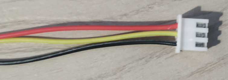
After I connected ADC wrong (GND<->v3.3) ADC got really hot, but no damage was done.
Thrustmaster t3pa pedal Load Cell Mod | Simonas G
Based on some forum posts, blogs and this Youtube Video I made a load cell pedal mod.
https://slowlogicboy.github.io//electronics/sim%20racing/TM-T3PA-LoadCellMod/