SpenceKonde / megaTinyCore

Arduino core for the tinyAVR 0/1/2-series - Ones's digit 2,4,5,7 (pincount, 8,14,20,24), tens digit 0, 1, or 2 (featureset), preceded by flash in kb. Library maintainers: porting help available!
Other
551 stars 142 forks source link

Question: Possible to change the boot loader timing? #225

Closed JasXSL closed 3 years ago

JasXSL commented 3 years ago

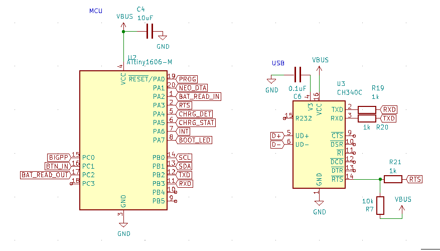
I've rigged up my attiny1604 to a CH340C USB to serial converter. And additionally connected PA3 to the CH340C RTS pin. Then added an interrupt that resets the attiny on level change. This allows me to write a sketch without having to manually reset the device, or needing to change the UPDI pin.

But this means the 8 sec boot time gets to be a bit excessive. Is there a way to change it? Any idea where I should start looking?

sideswiper22 commented 3 years ago

Yes, you are able to change the timeout variable of the bootloader but that involves building a new optiboot hex file. I asked Spence on how to do this a few months ago because I wanted to change the bootloader LED pin and this is what I did. You can refer to the optiboot repository for the steps and more details on building bootloaders.

For this, you will need an older version of the Arduino IDE (I use 1.0.6 for this) which has the old compiler tools such as avrgcc and make which are needed to build bootloaders. It doesn't have to replace your current version as you can simply get the portable zip version and store it in a folder somewhere.

After doing that, copy the "optiboot_x" folder and its contents from the 'megaTinyCore/bootloaders' folder to the 'hardware/arduino/bootloaders' folder of your 1.0.6 Arduino IDE directory. If you're on Windows, the megaTinyCore folder is at 'AppData/Local/Arduino15/packages'

Once that's all set, you can now start building bootloaders. You can refer to the Makefile in the optiboot_x folder by opening it with a text editor for recipes for all the megaTinyCore chip variants. Do note that bootloaders are the same as long they have the same number of pins. That means a bootloader for the 1604 can work with 1614, 804, 404, 414 etc.

In the Makefile: the recipe for the xxx4 variants is as follows: optiboot_txy4.hex UARTTX=B2 TIMEOUT=8 LED=A7

To build a bootloader, you can just create a bat file within the optiboot_x folder with contents in the following format: call omake -f makefile <filename> <settings> You can refer to the optiboot repository and wiki for all the available settings and commands.

For the bootloader you need, simply create a .bat file in notepad with the following contents: call omake -f makefile optiboot_txy4.hex UARTTX=B2 TIMEOUT=1 LED=A7 I simply replaced the timeout from 8 to 1 to mimic the behavior of the reset pin variant.

After this, run the bat file and copy the hex file you just generated back to the optiboot_x folder in the megaTinyCore directory.

NOTE that this will replace the default bootloader for the 14 pin, non-reset-pin variants. If you want to revert it, simply build another with the default settings.

If you don't want to overwrite the default bootloader, you can just rename "optiboot_txy4" in optiboot_txy4.hex to something else. You will then have to modify the boards.txt folder of the megaTinyCore directory by either adding a new board definition by copying the atxy4o variant, or by modifying this line: atxy4o.menu.resetpin.UPDI.bootloader.file=optiboot_x/optiboot_txy4{bootloader.uartswap}.hex

SpenceKonde commented 3 years ago

Thanks - note that the core comes with pre-built hex files for 1 second and 8 second bootloader timing.

JasXSL commented 3 years ago

Thanks - note that the core comes with pre-built hex files for 1 second and 8 second bootloader timing.

I'm seeing 4 different versions:

I'm assuming _rst is the one I'm looking for? Is there any documentation for what the alt is for?

sideswiper22 commented 3 years ago

Alt is for when you decide to use the alternate UART pins.

txyN is what you're looking for. txyN_rst is only used when you decide to disable your UPDI pin and turn it into reset (Which you cant re-UPDIfy unless you have a HV programmer. That's because in the boards.txt file, it actually switches between bootloaders depending on the settings you chose. You can see it doing that in these lines here:


atxy4o.menu.bootloaderuart.default=TX:5, RX:4 atxy4o.menu.bootloaderuart.alternate=TX:8, RX:9 atxy4o.menu.bootloaderuart.default.bootloader.uartswap= atxy4o.menu.bootloaderuart.alternate.bootloader.uartswap=_alt ...... atxy4o.menu.resetpin.UPDI=UPDI (powercycle to enter bootloader) atxy4o.menu.resetpin.UPDI.bootloader.file=optiboot_x/optiboot_txy4{bootloader.uartswap}.hex atxy4o.menu.resetpin.UPDI.bootloader.resetpinbits=01 atxy4o.menu.resetpin.reset=Reset (DANGER - Read docs first!) atxy4o.menu.resetpin.reset.bootloader.file=optiboot_x/optiboot_txy4{bootloader.uartswap}_rst.hex atxy4o.menu.resetpin.reset.bootloader.resetpinbits=10 atxy4o.menu.resetpin.gpio=IO (DANGER - Read docs first! powercycle to enter bootloader) atxy4o.menu.resetpin.gpio.bootloader.file=optiboot_x/optiboot_txy2{bootloader.uartswap}.hex atxy4o.menu.resetpin.gpio.bootloader.resetpinbits=00


As you can see with the sixth line, choosing to keep the UPDI pin as it is will make the Arduino IDE use the txyN variant of the bootloader as it is the default one.

What you can do though, is copy the recipe for the txyN_rst variant, and build a bootloader as the txyN variant. Since the recipe is technically the same as the one I recommended to you in my first comment and has the 1-second timeout setting. Another way you can do it is to change what file Arduino uses when still using UPDI to the _rst.hex file

sideswiper22 commented 3 years ago

Thanks - note that the core comes with pre-built hex files for 1 second and 8 second bootloader timing.

You're welcome! This is weird, from what I can find right now, it's only the _rst variants that have the one-second timeout.

SpenceKonde commented 3 years ago

Yes, that is the only difference in the hex file. The other change is in boards.txt to set the fuses differently. If you use that hex with normal fuse settings, you just get 1 sec reset timing.


Spence Konde Azzy’S Electronics

New products! Check them out at tindie.com/stores/DrAzzy GitHub: github.com/SpenceKonde ATTinyCore: Arduino support for almost every ATTiny microcontroller Contact: spencekonde@gmail.com

On Fri, Sep 18, 2020, 11:58 sideswiper22 notifications@github.com wrote:

Thanks - note that the core comes with pre-built hex files for 1 second and 8 second bootloader timing.

This is weird, from what I can find right now, it's only the _rst variants that have the one-second timeout.

— You are receiving this because you modified the open/close state. Reply to this email directly, view it on GitHub https://github.com/SpenceKonde/megaTinyCore/issues/225#issuecomment-694949669, or unsubscribe https://github.com/notifications/unsubscribe-auth/ABTXEW6DSJXJ62KPQEALFITSGN7TFANCNFSM4RPG55IA .

JasXSL commented 3 years ago

Thank you, it works!

Documentation for anyone who might stumble upon this issue and wonder how it's all setup (in windows):

Software

  1. Add the 1s option to the bootloader by editing the boards.txt file (probably in one of the following directories): C:/Users/<user>/AppData/Local/Adruino15/packages/megaTinyCore/harware/megaavr/<version>/boards.txt or C:/Users/<user>/Documents/Arduino/hardware/megaTinyCore/megaavr/boards.txt Make a backup of it before you start editing. Also make a backup when done editing since it'll be overwritten when you update the board library.

  2. Find the line that corresponds to the board you want to use followed by (optiboot). I'm using a 1604 so:

##############################################################

atxy4o.name=ATtiny1614/1604/814/804/414/404/214/204 (optiboot)
  1. Find the section under there that starts with atxy(nr)o.menu.resetpin.. Since i was using 1604 it was atxy4o.menu.resetpin.. Find the 3 lines followed by .UPDI. (in my case atxy4o.menu.resetpin.UPDI) and copy paste them.
  2. Change .UPDI on all 3 lines to something like UPDI_Short.
  3. Change the first line description to something distinct (I just added 1s after UPDI).
  4. Add _rst to the file name on the second line.
  5. Don't change the third line, resetpinbits should be 01 or you won't be able to easily reprogram it.

This is what I added:

atxy4o.menu.resetpin.UPDI_Short=UPDI 1s (powercycle to enter bootloader)
atxy4o.menu.resetpin.UPDI_Short.bootloader.file=optiboot_x/optiboot_txy4{bootloader.uartswap}_rst.hex
atxy4o.menu.resetpin.UPDI_Short.bootloader.resetpinbits=01
  1. Restart arduino if it's running. Select the board followed by (optiboot). In my case ATtiny1614/1604/814/804/414/404/214/204 (optiboot). The UPDI/Reset pin submenu will now have the UPDI 1s option.

Hardware

  1. First off, you'll need a UART/serial converter. Such as Adafruit FTDI friend or a good ol CH340. Connect power, ground, RXD from the converter to TXD on the board, and TXD on the converter to RXD on the board. And also connected power/ground obviously (and D+/D- when using CH340).
  2. I also connected RTS to PA3 and through a 10k resistor to 5V for auto reset. This requires a soft reset programmed in your sketch to work properly. After burning the bootloader, it kept rebooting until I uploaded my first sketch. But otherwise make sure to reset your device by toggling power to it when writing your first sketch, or if not using the auto reset.
  3. Finally I connected an LED on PA7 through a 1k resistor to ground, which flashes when the bootloader starts.

Sketch

  1. Setup an interrupt to reset the board whenever PA3 changes. Directly under setup(){ I added pinMode(10, INPUT) (10 is PA3 on the board I used). I'm sure you can set it up using the port flags directly, but I'm lazy. Then followed by PORTA.PIN3CTRL=0x1; in order to turn on interrupts on that pin, and sense CHANGE (worked best for me).
  2. Somewhere above setup() add the ISR function:
    // PA3 = 0b1000 (8)
    ISR(PORTA_PORT_vect) {
    byte flags=PORTA.INTFLAGS;
    PORTA.INTFLAGS=flags; //clear flags
    if( flags&8 )
        _PROTECTED_WRITE(RSTCTRL.SWRR,1);
    }
    

If that's the only interrupt you need in your sketch on that port, you could probably get away with just putting _PROTECTED_WRITE(RSTCTRL.SWRR,1); in the function, because I'm assuming resetting the MCU also reset the intflags? I haven't tried it tho, so don't take my word for it. Also note that if you pick a different pin for your interrupt, the flag will have to change as well. You can refer to the datasheet for it.

In either case, at this point I'm now able to:

  1. Burn bootloader using an arduino with the traditional JTAG/UPDI method.
  2. Plug it in with USB and upload sketches without needing to touch anything on the board.
JasXSL commented 3 years ago

Might wanna reopen as using the _rst version for UPDI no longer works in 2.1.

In 2.0.5, using optiboot_txy6_rst.hex with UPDI blinks once a second and accepts uploads In 2.1.5, the bootloader LED doesn't blink at all, and refuses uploads

Think it'd make sense to have a 1 sec startup time version in the library by default? With a CH340 you can have it auto reset the MCU right before it starts the upload, making the 8 sec excessive.

SpenceKonde commented 3 years ago

Wait what?!

SpenceKonde commented 3 years ago

Also, without configuring the UPDI pin as reset, how do you have the CH340 reset the chip? If you do configure the pin as reset, then it does use the 1 sec version by default (that's why it's included in the package, and why it's named _rst)

Also, closing this and creating new issue for the bootloaded issue.

JasXSL commented 3 years ago

I use a software reset on state change on PA3 (tho any pin works for this), and wire RTS to that through a 1k resistor, and a 10k pullup. The only caveat is that the device resets when you connect to it with serial the first time, and right at the start of the compile.

It looks like this and once you've burned the bootloader and make sure you always include the reset interrupt in your sketch, lets you program it with USB like any Arduino:

Schematic