Closed szymonk159 closed 2 years ago
The good news is that you don't get a time-out like last time, so basically the first problem has been resolved. This time, however, only some files #required
are actually loading - which indicates that the Forth words corresponding to the file name are already in the dictionary.
Could it be that you flashed the file STM8S001J3RS485-forth.ihx
(which already contains all the STM8EF-MODBUS Forth code) and not the "empty" file STM8S001J3RS485.ihx
?
Hint: it should be possible to do a fresh start by typing RESET
- even if the ihx file ending in "-forth" was used.
Thanks for answer. I fixed this problem by flashing STM8S001J3RS485.ihx file as you recommended. Previously I flashed STM8S001J3.ihx. Now uploading files stops during #require :NVM but console on PC5 started working. Probably it is a problem with POSTPONE word.
That's an interesting error message :-)
I think that you're using the lib
folder from a recent release of STM8 eForth which now uses POSTPONE
instead of [COMPILE]
and COMPILE
in the word :NVM
.
The library word :NVM
packaged in the zip file in the releases folder uses [COMPILE]
like the Forth image packaged there.
Please try the following:
lib
folder in your working directory lib
folder in the STM8EF-Modbus release fileWhile you're at it please check if target
in your working directory is a symlink to out/STM8S001J3RS485/target
(e.g. ln -s target out/STM8S001J3RS485/target
)
Thank you for answer. My working directory is stm8ef-modbus file. I copied lib,out and target files from stm8ef-bin folder. So the problem is that my Forth uploaded on board is 2.2.24 and I am using lib out and target files based on 2.2.27 Forth version ? (https://github.com/TG9541/stm8ef-modbus/issues/36 I flashed this on my board) How can I find lib from 2.2.24 version or how can I upload STM8S001J3RS485 working with 2.2.27 Forth image because newest release binary does not include STM8S001J3RS485 folder. Or maybe should I flash STM8S001J3.ihx from the newest binary release?
Please flash the file STM8S001J3RS485.ihx
from the out
folder in the release 0.20 archive stm8ef-bin.zip below. The folders mcu
and lib
there are the ones to use with the binary.
Thank you. Now it is working. Do you have any tutorials or advices how can I implement reading temperature in this protocol? I found some comments in board.fs file about using I2C and reading inputs but there is no ready implementation ?
There is indeed an interrupt-driver for the STM8 I2C peripheral: mcu/I2CMA
. Check out the I2C master examples code.
Hi. And what about 1 wire protocol because this sensors have small sizes and maybe it will be easier than i2c? Can I find some informations about it and implementation in Forth? I want to read temperature using modbus and openhab. Thank you in advance.
Sure, that has been done before - there is a simple stand-alone application and one that uses the 1-Wire solution for CamelForth by Brad J. Rodriguez. The second one assumes a more recent version of the STM8 eForth kernel (but, I believe, it can be made work with the one you're using now).
Okay thank you. So now I have working modbus rtu protocol with slave ID 1 (my stm8s103 board). To add temperature sensor (DS18B20) with 1 wire connection I should just upload this 1Wire.md code on my board and then it will be transfering data with my board all time or I should initialize it somehow in modbus protocol like IN@INIT in C0135 project.
I would start gaining some experience with the 1-Wire "simple stand-alone application" (1w.readrom
is what you need).
In the next step I'd extend the minimal FC04 "Read Register" by reading the temperature sensor directly instead of accessing a register in line 34 with 2* inputs + @
.
I am new to Forth but hopefully I can handle it. Thank you for help.
I'll lend you a hand. This is for the first step, reading the ROM of a 1-Wire sensor with the command $33 "Read ROM". This should work for getting a reaction from a single 1-Wire sensor - for more than one sensor you'll need the addresses of each of them, or you need to use the discovery method implemented in Brad's code.
Hint: if you need to use a different port pin than PB4 you may need to change the \res export
line and the gpio...
definitions.
\ STM8 eForth "1-Wire" communication primitives
\res MCU: STM8S103
\res export PB_DDR PB_IDR
#require ]B!
#require ]B?
#require ]CB
#require ]BC
#require :NVM
#require ALIAS
: gpio.d ( -- a c ) PB_DDR 4 ; \ literals for DDR GPIO
: gpio.i ( -- a c ) PB_IDR 4 ; \ literals IDR GPIO
:NVM ( -- ) \ GPIO low / dominant
[ 1 gpio.d ]B!
;RAM ALIAS 1w.l
:NVM ( -- ) \ GPIO floating / input
[ 0 gpio.d ]B!
;RAM ALIAS 1w.f
:NVM ( n -- ) \ wait n x 2us @16MHz
FOR [ $9d9d , $9d9d , $9d9d , $9d C, ] NEXT
;RAM ALIAS x2us
NVM
: 1w.res ( -- f ) \ 1-wire reset with presence check
1w.l 240 x2us 1w.f 30 x2us [ gpio.i ]B? NOT 210 x2us
;
: 1w.t ( c -- c ) \ 1-wire transfer c -> c
7 FOR
1w.l 1 x2us
[ $6401 , \ SRL (1,X)
$8C C, \ CCF
gpio.d ]CB 3 x2us [ gpio.i ]BC
[ $76 C, ] \ RRC (X)
12 x2us
1w.f 1 x2us
NEXT EXG
;
VARIABLE RomID 14 ALLOT
: 1w.readrom
1w.res
$33 1w.t drop
7 FOR
$FF 1w.t
[ RomID 7 + ] LITERAL I - C!
NEXT
;
RAM
For testing the sensor run this from the console:
RomID 16 ERASE
: test
1w.readrom
RomID 10 DUMP
;
Thank you. I will test it as soon as my temperature sensor arrives.
I connected sensor to PB4 ,wrote RomID ERASE and test definition and console is showing this:
Great, you're getting the ROM address of the sensor - I've been experimenting a bit with the commands $CC (skip), $44 (convert) and $BE (read scratchpad) - I'll have to try some more tomorrow.
Okay, thank you. I hope this commands will be working and will allow to read temperature. I will be grateful if you will share how to implement it with me. Also I have a question about C0135 board. Today it arrived to me and I want to use DS18B20 sensor also. Is it possible ?
Sure, using the inputs of the C0135 to connect DS18B20 sensors is possible (depending on how you see it the unprotected inputs of the board are a feature or a hazard. In this case it's a feature).
You can even use one of the inputs as a sensor VCC output (3.3V, up to 5mA - that's enough for many sensors if temperature conversion is done one at a time).
I'm still figuring out the easiest/safest way to do a conversion.
I assume that you know the address of your sensor.
Questions:
Here is a simple implementation for reading temperature values from one or multiple sensors.
https://gist.github.com/TG9541/fe63109242bf18a37853691197c2dd0b#file-1w-ds18b20-fs
Hint: for working with a single sensor you don't need to know the ROM-ID. For more than one sensor you need to know the ROM-IDs, as shown in the example part:
1w.readrom \ read ROM of single sensor to RomID
RomID 8 DUMP \ show ROM Id, should start with $28
\ example for fixed/known sensor ID
CREATE MYSENSOR $28 C, $88 C, $16 C, $76 C, $E0 C, $01 C, $3C C, $0A C,
: testid ( a_id -- ) \ read the scratchpad from a sensor with ROM-ID stored at a_id
DUP 1w.match 1w.conv
1w.match 1w.scratch
scratch 9 DUMP
;
RomID testid \ read the full scratchpad
: testsingle ( -- n ) \ if just one sensor is connected the ROM-ID needs not be known
1w.skip 1w.conv
1w.skip 1w.sens
;
testsingle . \ conversion takes 750ms, so better repeat this
I dont have my sensor ID but I think this adress is proper because it starts with 28. I need one sensor for now. I implemented this and results are on this screen. Is this scratchpad data proper? Thank you in advance.
This looks OK, assuming that you to tested the sensor by heating it briefly.
Your ROM-ID is $28 $A $F7 $8A $D $0 $0 $F4
, so it can be defined like this:
CREATE MYSENSOR $28 C, $A C, $F7 C, $8A C, $D C, $0 C, $0 C, $F4 C,
If you use a single sensor 1w.skip
can be used instead of 1w.match
. This means that for starting the conversion and for reading the scratchpad no ROM-ID will be needed.
The scratchpad data looks normal - Byte0 and Byte1, the ones that can be accessed with 1w.sens
, contain the sensor data from the last time you called 1w.conv
. Byte4 is $7F which means that your sensor is in 12bit mode (that's the default) and the sensor readout from 1w.sens
needs to be divided by 16 (the first temperature is about 22.2 C and the peak temperature is 30.9 C).
Okay, thank you very much. So now to run it by modbus this 2 data bytes (byte0 and 1) need to be stored in holding registers and then I will be able to read temperature using modbus?
You'll have to make sure that the sensor readout gets refreshed every so often (depending an the rate of the temperature change).
How fast do you intend to read the "holding register"?
If that happens periodically, e.g. with a rate of 1s, it's possible to do read the sensor in a custom FC03-handler (first use 1w.sens
, write the result to a "holding variable", then use 1w.conv
to prepare a conversion for the next transfer).
Polling rates below 1s require some more effort. In that case take into account that the sensor needs >750ms for a single conversion. Faster conversion rates require a resolution trade-off.
I think that it is not necessary to be often. I am creating basic program for smart homes based on modbus for my engineer's thesis. I think that reading temperature in room can happens less frequently.
In that case a rate of 1s is more than enough - that would be sufficient for sensing that a window has been opened.
If you start from the other side I'd recommend that you look at the FC03 code here.
A word like the following might be what you need:
: DS18B20.sens ( -- n )
1w.skip 1w.sens
1w.skip 1w.convert
;
The FC03 handler could then be hacked like this:
\ FC03 handler
:NVM ( -- )
DS18B20.sens holding !
[ ( xt xth ) SWAP ] LITERAL 16 ( xt bpu ) mbread
;NVM ( xth ) 3 FC>XT !
Okay, I modified MBSERVER by adding this DS18B20.sens word. ( I changed this 1w.convert into 1w.conv because 1w.convert was not recognized). I also changed FC03 handler as you recommended. . How can I check in Forth console if FC03 handler is working, because in qModMaster when I was reading register with 0x03 by function code it was showing 00 only.
Can you please post your FC03 handler code? Does reading with other FCs work, e.g, FC04?
This is MBSERVER. I just changed FC03 code. Maybe I should implement it in board.fs? There are some comments about reading temperature by I2C. qModMaster is showing only 00 when I am using funcions 0x03 or 0x04 but when I am writing multiple coils first try is showing time out but then I can write vaules and "values written correctly" appears.
Writing and reading should work reliably (as shown here).
Also, if an FC03 access happens typing holding ?
on the console should show a fresh value.
Please test if other Modbus FCs work. By using one of the minimal demo servers in ./test
you'll get a console output.
Functions are working fine. I checked in qModMaster. But where the data from temperature is stored? Can I get access to this holding registers with data from sensor by using qmodmaster?
Great to see that the communication works! You're using "Holding Register" start address "2" - we've been writing into the first 16bit cell. I would try reading from the first (I don't remember if that is Start Address "1" or "0").
Hint: by writing a non-zero value to the 2nd cell, e.g., $AA55 holding 2+ !
the question "where does it start" is easier to answer.
By increading the value of HOLDINGCELLS
(by default this is 2) you can also use more "Holding Registers".
Okay thank you so much, it is working now! I changed start addres to 0 and response from the first slave is a value about 0168 hex so 360 dec and it is correct. So in the future I can add more sensors, find their ID, write reading temperature words for each sensor and save data from each to different holding register addres?
Yes, that's correct. You can simply create an array of sensor ROM-IDs and address the sensors with the index of the "Holding Register".
If you need a higher rate of temperature measurements it's also possible to issue 1w.conv
in a "background task triggered idle task". That should be relatively simple to do (I can provide some example code) and reading from a "holding register" would always return a fresh value.
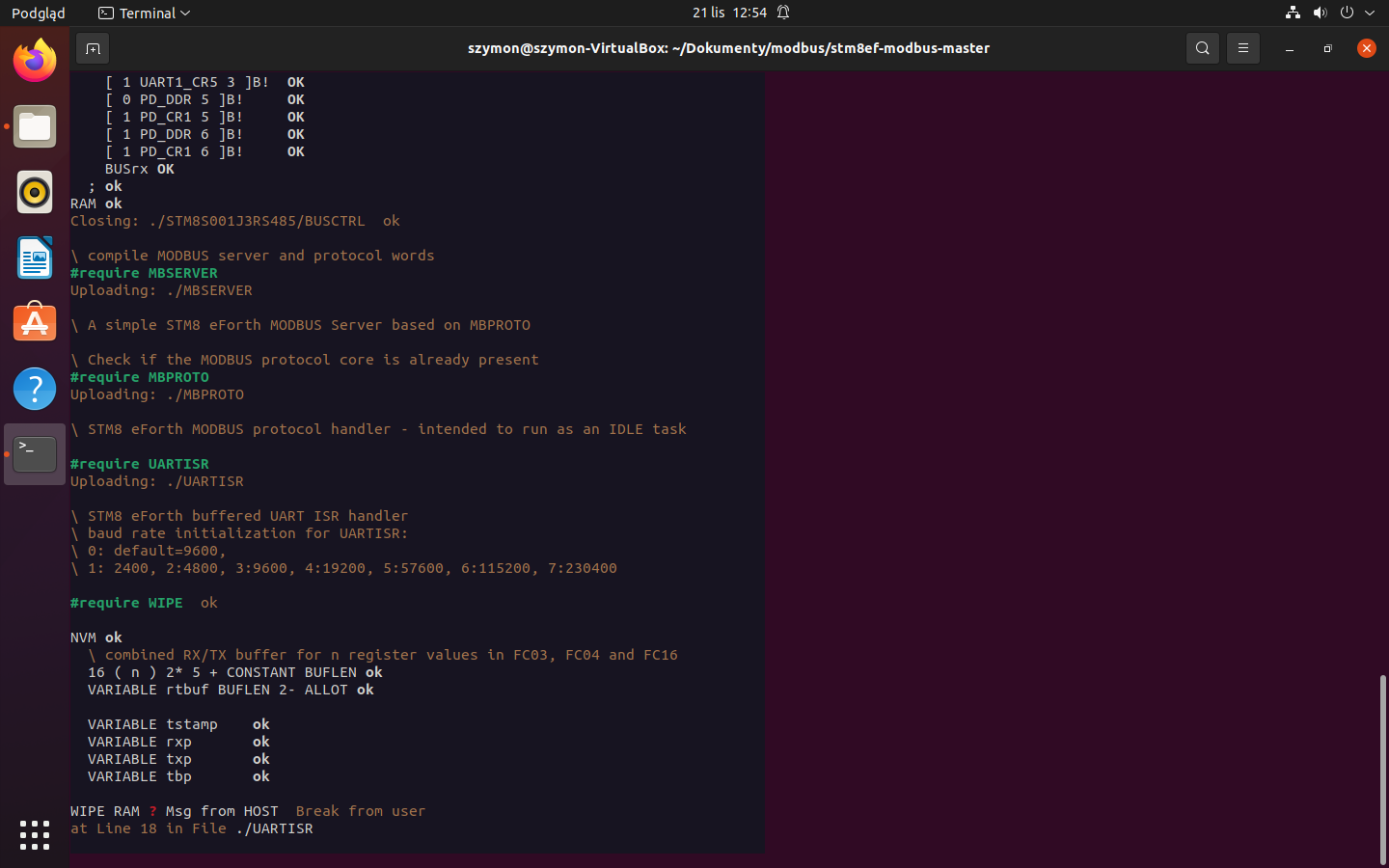
Yes, you can show me some example code. Maybe it will be usefull for me. In this week I will download openhab and I will try to read temperature by modbus using openhab.
@TG9541 It is me again. I don't know how to reopen last issue so I created the new one. I sucessfully downloaded STM8S001J3.ihx as you recommended on my STM8S103F3 board. Then I wanted to upload modbus protocol from STM8S001J3RS485 file using halfduplex on PD5 pin but during compilation it stops on uploading WIPE RAM at line 18 in UARTISR file and I dont know why. Firstly I uploaded BUSCTRL and console shows ok. After #include STM8S001J3RS485/board.fs I have some problems. My purpose is to download modbus protocol on my board and then add temperature sensor and read temperature by modbus. Do you have any advice? Thank you very much in advance.