TadPath / PUMA

3D Printed Microscope
GNU General Public License v3.0
613 stars 47 forks source link

Power lamp motherboard connection #22

Closed GanescuStefan closed 2 years ago

GanescuStefan commented 2 years ago

Hello,

I am currently trying to build the PCC and I am wondering what the "JST3 Pwr Lamp" on the motherboard is attached to. In the assembly procedure it mentions that the output of the buck converter should be connected to the lamp meter section of the motherboard, while the batteries should be connected to the motherboard "JST1 Power In" through a switch.

image

Is the lamp power meant to be attached to the input of the buck converter or to some other part? I would appreciate a circuit diagram of some sort if possible, as it would be much easier to see it than through text.

Thank you in advance

TadPath commented 2 years ago

Hello. JST3 provides the power going to the input of the XL4015 power regulator (that is what provides power for the lamp - Pwr Lamp). As with all PUMA modules - as I state in the GitHub intro - the video will make all things clear but I have not yet finished the PCC video so it is not yet released. You may get some additional insight into lamp connections with respect to the potentiometer by looking at the pages on the PUMA Lite. Here is a photo from a screenshot of one of my video clips (from the as yet unreleased video!) showing me about to make the connection:
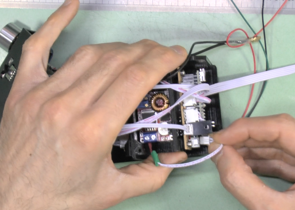
 image

GanescuStefan commented 2 years ago

Thank you very much! Does this mean that the JST 9 Lamp Meter connection is attached to the input from the XL4015 power regulator instead?

TadPath commented 2 years ago

Sorry. I made a mistake in my last reply description - JST3 provides power to the INPUT side of the XL4015 (I edited my answer to reflect that). The photo is correct. I see that it is precarious to try and answer such questions one-by-one and probably others can't wait for the video too (it will take me a few months at least anyway to finish it) so, I made a connections diagram and posted that on the Motherboard page here on GitHub now. Please see the diagram - it should answer all your questions about connections. As for practicalities about wire lengths, insulation, techniques for making the various connections - you will have to work that out for yourself till the video comes out (you may even work out better methods than mine anyway). The video will take time because I am actually making some upgrades / alterations to the PCC (as will all PUMA modules prior to video release) so watch out for the video when it comes because you may want to update your PCC accordingly.