The-EG / OctoPrint-UBLMeshEdit

An OctoPrint plugin that can be used to view, edit and manage Marlin Unified Bed Leveling (UBL) meshes.
GNU Affero General Public License v3.0
17 stars 5 forks source link

[WIP] Add Interactive Probing Mode #8

Open The-EG opened 3 years ago

The-EG commented 3 years ago

Adds a checkbox above the mesh display to enable 'Interactive Probing Mode.'

image

When checked, this will display a warning: image

This warning can be hidden with a setting Hide warning when enabling.

If the user decides to proceed, the gcode commands specified in the Pre-GCode Commands setting are sent to the printer: image

And a message is displayed: image

At this point, selecting a point will do the following, in addition to the current behavior:

  1. Move up to Z Hop at Z Feedrate (plugin settings): G0 Z{zHop} F{zFeed}
  2. Move to the selected point at X/Y Feedrate (plugin setting): G42 I{i} J{j} F{xyFeed}
  3. Move down to Z at Point (plugin setting): G0 Z{zAtPoint} F{zFeed}

The settings referenced above are configurable: image

Feedrates are specified in mm/s but are converted to mm/min when sending commands to the printer.

When the user unchecks the checkbox to disable Interactive Probing mode, the Post-GCode Commands are sent to the printer: image

Current functionality in action (click for video):
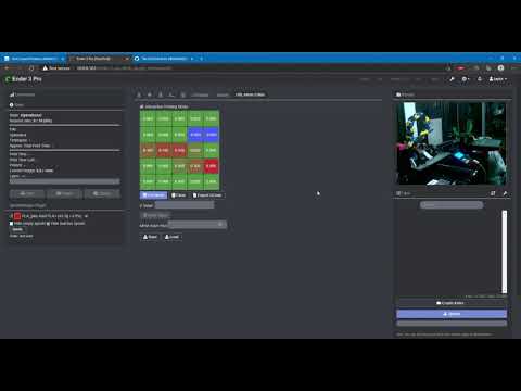
 WIP Interactive Probing

Todo:

Fixes #2

The-EG commented 3 years ago

This feature can be tested out by installing the plugin from this branch's URL: https://github.com/The-EG/OctoPrint-UBLMeshEdit/archive/feature/interative_probing.zip

No uninstall is necessary, just install over the existing.

To get back to the current release you can always just re-install the main URL: https://github.com/The-EG/OctoPrint-UBLMeshEdit/archive/main.zip

lightmaster commented 3 years ago

Z Hop and Z at point, if the commands are set like G1 Z{zhop}, then can we add a warning that the value should be enough for your probe to clear the bed? Like my probe offset is about -16mm, so I'd have to use a ZHop of at least 17mm, probably 20 to be safe.

The-EG commented 3 years ago

Z Hop and Z at point, if the commands are set like G1 Z{zhop}, then can we add a warning that the value should be enough for your probe to clear the bed? Like my probe offset is about -16mm, so I'd have to use a ZHop of at least 17mm, probably 20 to be safe.

Yes, that is the intent and having a description/warning for those settings makes sense. I think have a similar situation, since I use a digital indicator (like a dial gauge) so I need a few mm for it to clear, but no where near 16mm...

I'm guessing you'd have to alter the Z at Point value by 16 as well?

lightmaster commented 3 years ago

I'm guessing you'd have to alter the Z at Point value by 16 as well?

Yes. Whenever using the probe, it hits the bed at about 16mm, whereas nozzle hits at 0mm. So if doing a quick calibrate with the probe, I'd have to have at least 16 mm clearance, if doing a careful calibration, then I'd use the nozzle itself with very low ZHop and Z at Point values.

Users would need to understand that if they set it to 5mm while they have a probe attached that needs say 10mm of clearance, that probe will crash into the bed.

bpengu1n commented 2 years ago

Is this in a relatively usable state as is? Anything I could contribute to help push it over the line?

The-EG commented 2 years ago

@bpengu1n It functioned as I described when I last worked on it. However, I never moved forward with it because I had some major concerns.

There are really 2 use cases that I know of for this type of functionality:

  1. Users who want to move the nozzle to the selected mesh point as an indicator, ie. 'where on my bed is this point?' Probably most helpful in cases where the user has printed a test pattern and is trying to determine which point needs to be adjusted.
  2. Users who don't have an LCD on their printer capable of performing G29 P4, and want to use this UI as a replacement.

1 is very straight forward and is fairly low risk. It's really a matter of making sure the user can't initiate that behavior during a print and other measures, and running an appropriate command (G42). I don't have to worry about mesh insets, size, etc. because the firmware does all of that with the command.

2 also seems somewhat straight forward, but the complication comes when the user also wants to use a mounted probe, with offsets. As I began working on that, I realized that the risk of a user not understanding the options and the intent of the mode, and damaging their printer was fairly high. And this also begins to increase the complexity of the plugin and what it's trying to do by quite a lot. In contrast to 1, just moving to the proper point would now require the plugin to know the bed size, the mesh insets, the probe offsets, and the min and max travel on all axes (ie. X_MIN_POS, etc from Marlin).

Considering that, I didn't feel that it would provide enough benefit for the effort and risk required. I'd be willing to revisit, however.