 radensb
commented
4 years ago
radensb
commented
4 years ago Open pmozbert opened 4 years ago
radensb
commented
4 years ago  johnboiles
commented
4 years ago
johnboiles
commented
4 years ago That page references the "the cold-junction mod as described in the Wiki". Sounds like there should be another page for the Maxim 18B20. I ran into the same thing today.
 m-kozlowski
commented
4 years ago
m-kozlowski
commented
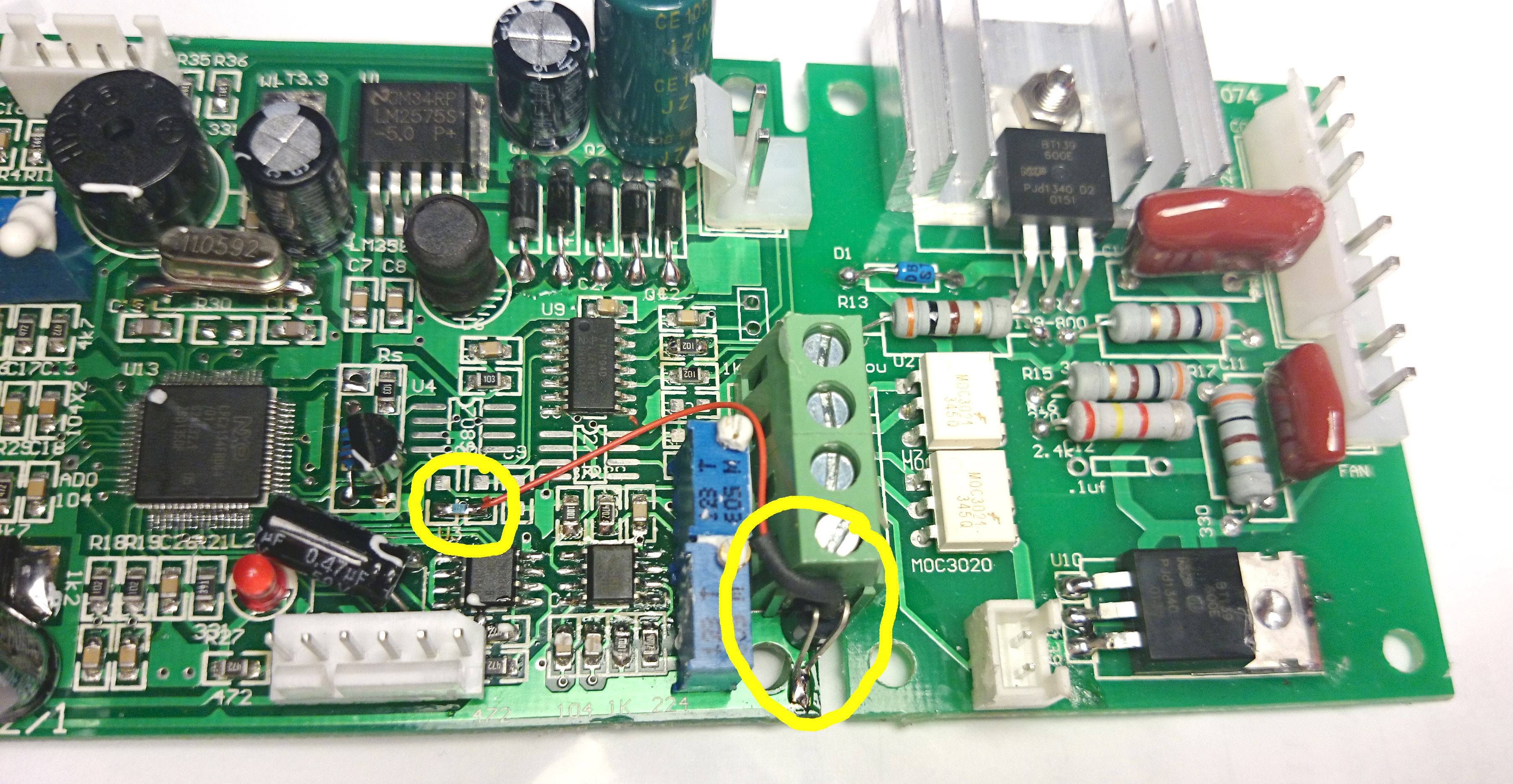
4 years ago There is no dedicated page, as far as i know. The best documentation for 1wire mod is the "Cold junction compensation" paragraph of README.md along with this image from the wiki start page
 pmozbert
commented
4 years ago
pmozbert
commented
4 years ago Thanks, I was hoping to find information about which pads to use on the board, though i can sort of make it out from the picture. And also the specifications for the resistor that must be added. Also, there are several variations of the Maxim 18B20. Some use parasitic power, others not. So it would be good to know exactly which one is being referred to. And finally, in the picture it shows 2 pins soldered to ground(?). But for the parasitic chip, one of the pins is NC. So I'm wondering why it's being also attached to ground.
m-kozlowski
commented
4 years ago all of the 18B20s I've used required pin3 connection to GND to work in parasite mode. If yours doesn't need that and have pin 3 unconnected, then soldering both pins to ground might still be good idea due to increased stability.
Resistor value (4k7) is mentioned in README.md, same as 18B20 documentation suggests. My guess is anything between 2 and 5K should work.
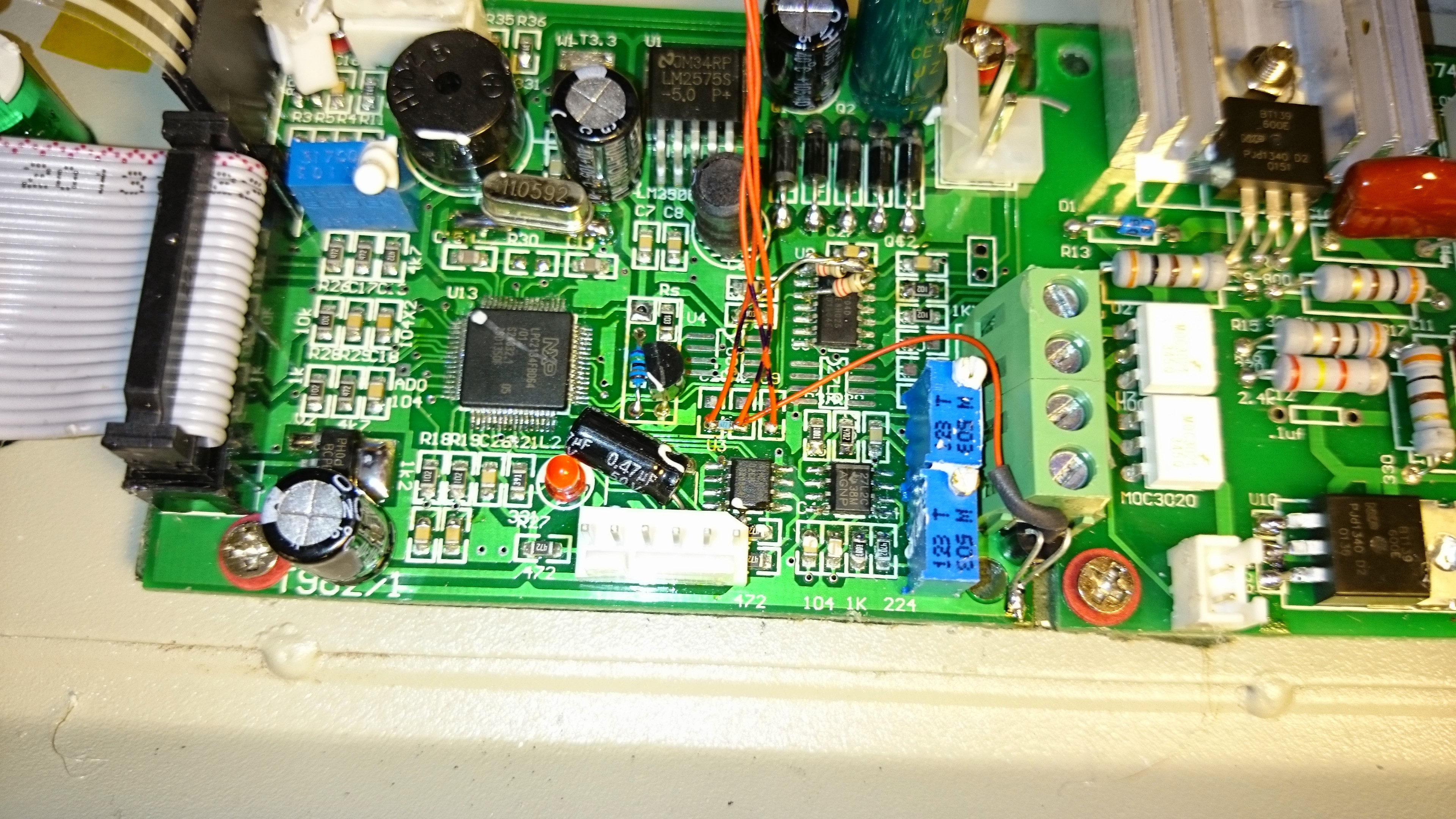
BTW, yeah, documentation here is quite messy and it took me a while as well to sort things up what and where to solder. Take a while and browse wiki, even unrelated pages, as you may find photos from different angles that gives better view. Like this one
 gcormier
commented
4 years ago
gcormier
commented
4 years ago Found a good video as well that covers it - indeed the Wiki is missing some basic info.
pmozbert
commented
4 years ago I was able to complete the mods. Here's a couple notes.
 karrots
commented
4 years ago
karrots
commented
4 years ago There are two part numbers for the DS18B20. 1) DS18B20 and 2) DS18B20-PAR. The -PAR model only supports parasitic power hence the NC pin. The non-PAR model supports powered mode or parasitic mode. When used in the parasitic mode you connect VCC to GND.
It's helpful to read the section titled Powering the DS18B20 in the datasheet to ensure proper power. They also don't suggest running in the parasitic mode above 100C.
https://datasheets.maximintegrated.com/en/ds/DS18B20.pdf https://datasheets.maximintegrated.com/en/ds/DS18B20-PAR.pdf
 jwestmoreland
commented
4 years ago
jwestmoreland
commented
4 years ago Hello All and just a comment:
It should be possible to power the PCB via the USB-Serial adapter. I did that when I took out the PCB - I'm using one of the cables from FTDI but I'm getting one of these C232HD-DDHSP-0 (URL: https://www.mouser.com/ProductDetail/FTDI/C232HD-DDHSP-0?qs=%2Fha2pyFaduibYjSO6Dz1ybsSG%252B9jH52tzwTckDaG7GOSJXKPayvYHw%3D%3D ) since you can use FLASHMAGIC to control the n_ISP and Reset_n via RTS and DTR.
Like what's mentioned on this site - the 3.3V rail is close to the ISP connector - on the RHS there's a 4.72K resistor that a pin can be soldered to. A pic on this site shows a connector and I believe that's the point where the soldering was done. I soldered to that with a standard 0.1" header pin and powered the PCB from that. Note, I had the board out of the chassis - I haven't tried this yet with the board in the chassis. I do want to look at the serial data when the unit is running, so I'm planning on adding the C232HD-DDHSP-0.
Plus, the part of the chassis grounding is mentioned on this site in several places. The apparent powder coat paint job is done so well as to make the top, bottom and back parts of the chassis electrically isolated. As pointed out - it's best to connect all major chassis components with a ground cable to the ground on the power connector, but you can also remove the paint on the ground connector and then remove paint on at least one of the metal screws for each of the major 3 chassis components and it should accomplish the same thing. As discussed here - on the originally shipped unit I received - the chassis ground was electrically isolated; making the unit dangerous should an electrical short occur. It would appear all conceivable improvements to the T-962(x) are discussed somewhere on this site or at least there's a link to it from this site. (Kudos to those that put all of this together.)
HTH, John W. PS - When I took the back panel off - a small piece of wood fell out - I wondered for a while where that came from - it was from the main rear fan enclosure area that was part of keeping the insulating material out of the way of the main rear fan. So, anyone doing this mod for the first time - make sure when you put things back together the main rear fan doesn't make contact with any of the insulating material for the oven or maybe the main fan won't spin when the unit is buttoned back up.
I see lot's of mentions of the cold junction mod with DS18B20 temperature sensor, but can't find the wiki page about how to do it. The closes I see is the one for the Dallas chip, but nothing for the 1-wire maxim chip.