 xnk
commented
2 years ago
xnk
commented
2 years ago I’m confused, I’d say the “original PID code of controller” is non-existent (I couldn’t see any trace of PID going on in the original firmware, that was a straight-up bang-bang controller). But the (supposedly) improved firmware in this repo looks like this last time I checked:
https://github.com/UnifiedEngineering/T-962-improvements/blob/master/src/reflow.c#L155-L175 https://github.com/UnifiedEngineering/T-962-improvements/blob/master/src/reflow.c#L155-L175
Note that the T-962-improvements code uses PID output limits that includes both the heating and cooling region, hence 255+248 where the output value of 248 means that neither heating nor cooling is active.
On 7 Jan 2022, at 10:44, Sevstels @.***> wrote:
The original PID code of the controller does not work correctly due to errors in the settings. It goes into "relay control" mode with a small linear section.
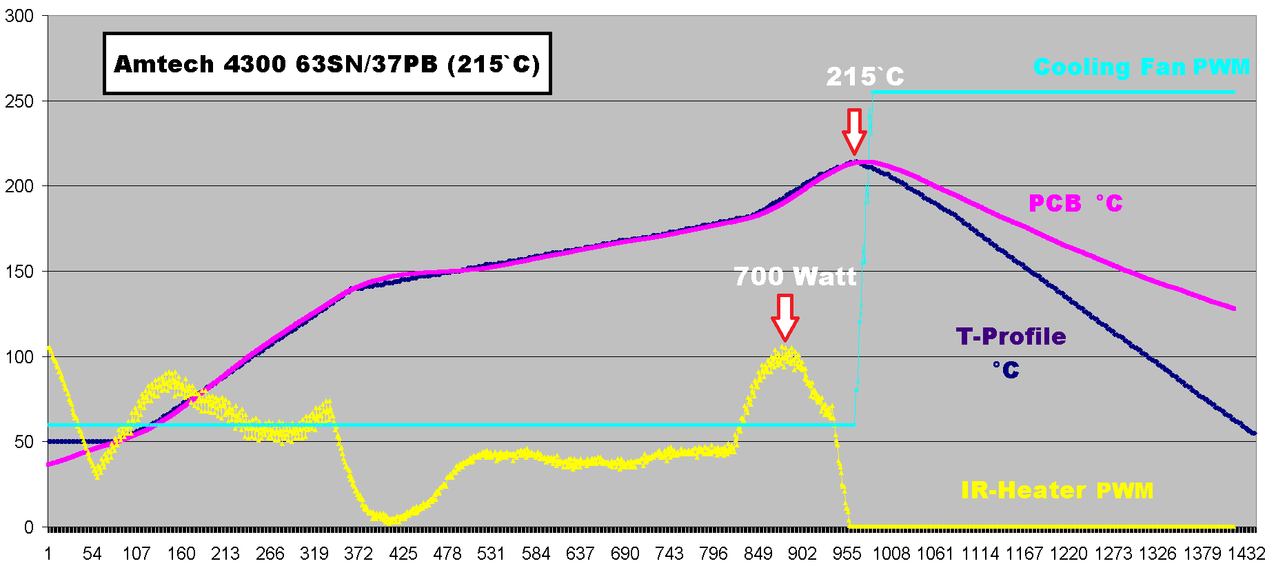
//Heater PWM modulator have range 0...255 del-> PID_SetOutputLimits(pid, 0, 0xffff); <-integrator will overflow here PID_SetOutputLimits(pid, 0, 0xff); <-correct value
//default Controller Sample Time is 0.1 seconds del-> SampleTime = 100; <- wrong sampling rate pid->SampleTime = 250; //250ms loop sample perod
— Reply to this email directly, view it on GitHub https://github.com/UnifiedEngineering/T-962-improvements/issues/221, or unsubscribe https://github.com/notifications/unsubscribe-auth/AAYSRDYEA335KRYLEMIKKXTUU2YXLANCNFSM5LOMZPNA. Triage notifications on the go with GitHub Mobile for iOS https://apps.apple.com/app/apple-store/id1477376905?ct=notification-email&mt=8&pt=524675 or Android https://play.google.com/store/apps/details?id=com.github.android&referrer=utm_campaign%3Dnotification-email%26utm_medium%3Demail%26utm_source%3Dgithub. You are receiving this because you are subscribed to this thread.
 sevstels
 mikeanton
 GitLang
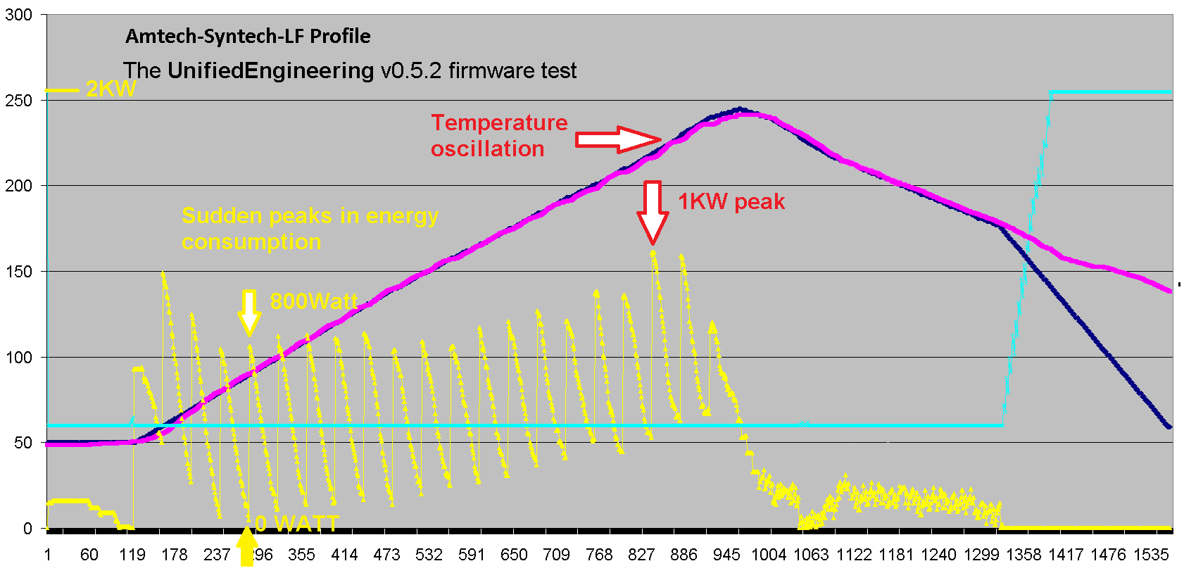
//Heater PWM modulator have range 0...255 del: PID_SetOutputLimits(pid, 0, 0xffff); <-wrong limit PID_SetOutputLimits(pid, 0, 0xff);
//default Controller Sample Time is 0.1 seconds del: SampleTime = 100; <- wrong sampling rate pid->SampleTime = 250; //250ms loop sample perod