 biomurph
commented
3 years ago
biomurph
commented
3 years ago @VladiLuzJr Thanks for using Pulse Sensor! Your signal does look small. I don't think you will have signal problems because of the sensors being too close. If you are using Arduino Uno, you should definitely use the interrupts. They make the result very accurate. I have not used this code base in a little while. I will try to replicate your problem and see if I can make it work.
Also, can you verify your hardware? Send a picture of your setup?
 VladiLuzJr


Signals oscillate in diferent Thresholds
Recently I have been engaged in my Conclusion Project of an technician course in electronics...
When trying to use two pulse sensors at once, in order to find PTT. I have received high variance values, while using Processing...
The sensor in Analog pin0 is located in the beginning of my hand thumb and the sensor in Analog pin1 is located at the tip of the same thumb. Is it possible that the two IR LEDs nearby can add noise to the signal, therefore creating this difference in Threshold?
Using windows 10 , Arduino UNO and PulseSensor Playground 1.5.1. I emphasize that the pulse graphics are tiny, even if I try "goldilocks pressure" : (
Is it possible that once both sensors are being powerd by de Arduino built-in 5v supply, they are acting like a current divider?
I have reason to believe that this errors may happen due to Arduino Interupts malfunction... Do I need to install some especific version of the Arduino IDE to use this define?
Once both signals oscillate in different levels, I think the PTT software cannot use the same Threshold for the pulse sensors...
In the pictures , the correspondig Processing GUI and Serial Plotter prints:
SerialPlotter_with_Interupts=False: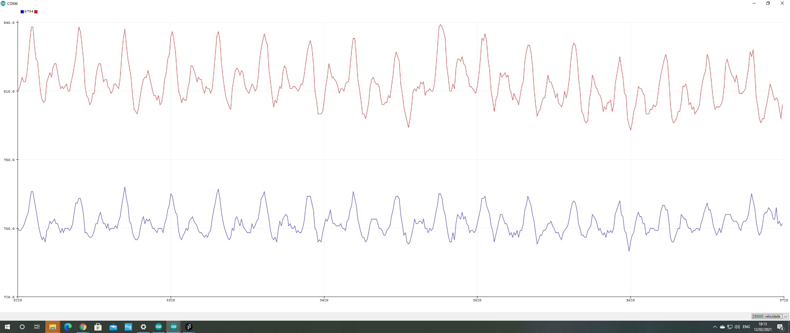
SerialPlotter_with_Interupts=True: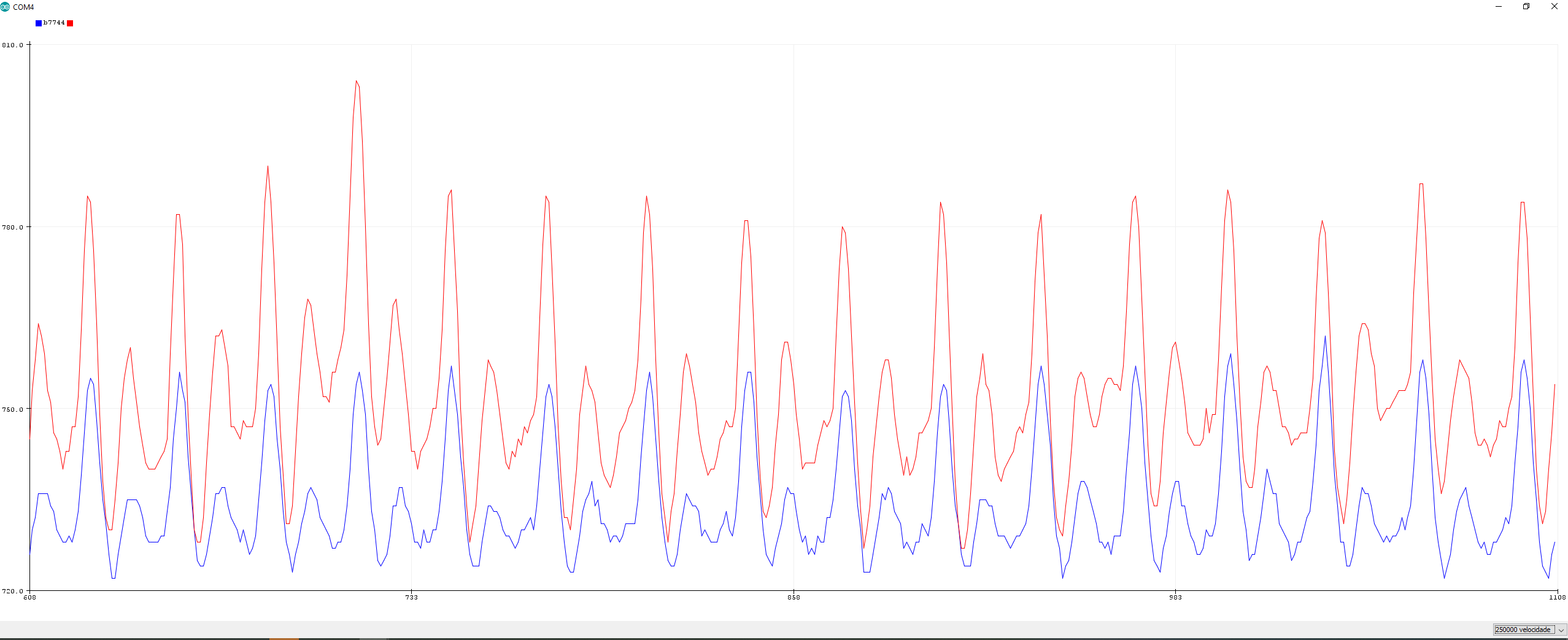
ProcessingGUI_with_Interupts=False: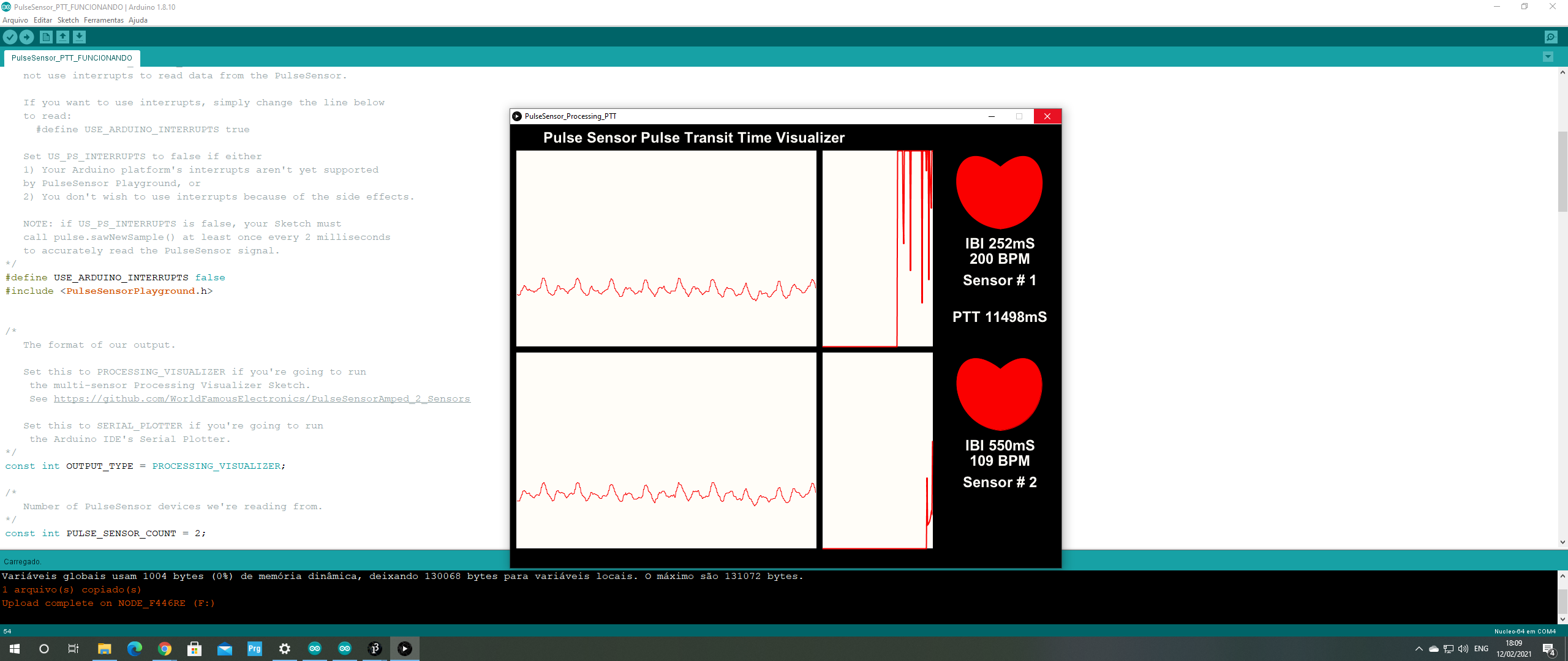
ProcessingGUI_with_Interupts=True: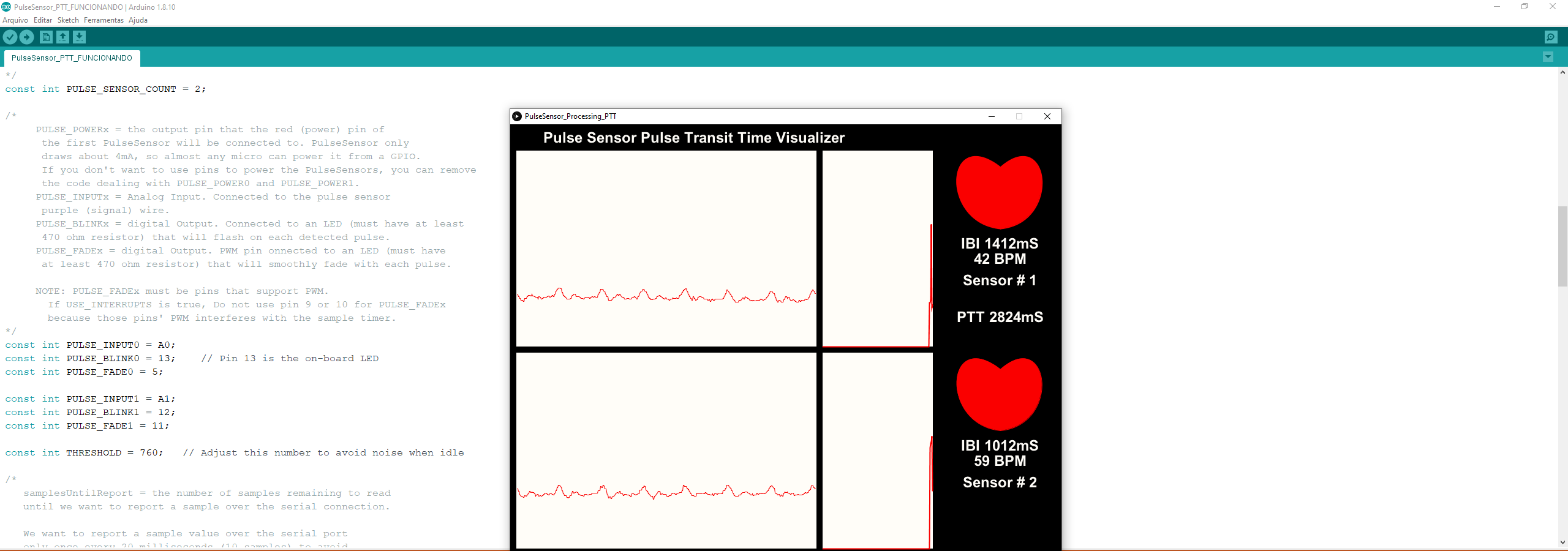
The .ino code is written as follows:
/* Arduino Sketch to detect pulses from two PulseSensors and measures the time between! This can be used to derive Pulse Transit Time (PTT)
Here is a link to the PTT tutorial https://pulsesensor.com/pages/pulse-transit-time
Copyright World Famous Electronics LLC - see LICENSE Contributors: Joel Murphy, https://pulsesensor.com Yury Gitman, https://pulsesensor.com Bradford Needham, @bneedhamia, https://bluepapertech.com
Licensed under the MIT License, a copy of which should have been included with this software.
This software is not intended for medical use. */
/* Every Sketch that uses the PulseSensor Playground must define USE_ARDUINO_INTERRUPTS before including PulseSensorPlayground.h. Here, #define USE_ARDUINO_INTERRUPTS false tells the library to not use interrupts to read data from the PulseSensor.
If you want to use interrupts, simply change the line below to read:
define USE_ARDUINO_INTERRUPTS true
Set US_PS_INTERRUPTS to false if either 1) Your Arduino platform's interrupts aren't yet supported by PulseSensor Playground, or 2) You don't wish to use interrupts because of the side effects.
NOTE: if US_PS_INTERRUPTS is false, your Sketch must call pulse.sawNewSample() at least once every 2 milliseconds to accurately read the PulseSensor signal. */
define USE_ARDUINO_INTERRUPTS true
include
/* The format of our output.
Set this to PROCESSING_VISUALIZER if you're going to run the multi-sensor Processing Visualizer Sketch. See https://github.com/WorldFamousElectronics/PulseSensorAmped_2_Sensors
Set this to SERIAL_PLOTTER if you're going to run the Arduino IDE's Serial Plotter. */ const int OUTPUT_TYPE = PROCESSING_VISUALIZER;
/ Number of PulseSensor devices we're reading from. / const int PULSE_SENSOR_COUNT = 2;
/* PULSE_POWERx = the output pin that the red (power) pin of the first PulseSensor will be connected to. PulseSensor only draws about 4mA, so almost any micro can power it from a GPIO. If you don't want to use pins to power the PulseSensors, you can remove the code dealing with PULSE_POWER0 and PULSE_POWER1. PULSE_INPUTx = Analog Input. Connected to the pulse sensor purple (signal) wire. PULSE_BLINKx = digital Output. Connected to an LED (must have at least 470 ohm resistor) that will flash on each detected pulse. PULSE_FADEx = digital Output. PWM pin onnected to an LED (must have at least 470 ohm resistor) that will smoothly fade with each pulse.
*/ const int PULSE_INPUT0 = A0; const int PULSE_BLINK0 = 13; // Pin 13 is the on-board LED const int PULSE_FADE0 = 5;
const int PULSE_INPUT1 = A1; const int PULSE_BLINK1 = 12; const int PULSE_FADE1 = 11;
const int THRESHOLD = 550; // Adjust this number to avoid noise when idle
/ All the PulseSensor Playground functions. We tell it how many PulseSensors we're using. / PulseSensorPlayground pulseSensor(PULSE_SENSOR_COUNT);
/ Variables used to determine PTT. NOTE: This code assumes the Pulse Sensor on analog pin 0 is closer to he heart. / unsigned long lastBeatSampleNumber[PULSE_SENSOR_COUNT]; int PTT;
void setup() { /* Use 250000 baud because that's what the Processing Sketch expects to read, and because that speed provides about 25 bytes per millisecond, or 50 characters per PulseSensor sample period of 2 milliseconds.
*/ Serial.begin(250000);
/ Configure the PulseSensor manager, telling it which PulseSensor (0 or 1) we're configuring. /
pulseSensor.analogInput(PULSE_INPUT0, 0); pulseSensor.blinkOnPulse(PULSE_BLINK0, 0); pulseSensor.fadeOnPulse(PULSE_FADE0, 0);
pulseSensor.analogInput(PULSE_INPUT1, 1); pulseSensor.blinkOnPulse(PULSE_BLINK1, 1); pulseSensor.fadeOnPulse(PULSE_FADE1, 1);
pulseSensor.setSerial(Serial); pulseSensor.setOutputType(OUTPUT_TYPE); pulseSensor.setThreshold(THRESHOLD);
// Now that everything is ready, start reading the PulseSensor signal. if (!pulseSensor.begin()) { /* PulseSensor initialization failed, likely because our Arduino platform interrupts aren't supported yet.
} }
void loop() {
/ Wait a bit. We don't output every sample, because our baud rate won't support that much I/O. / delay(20);
// write the latest sample to Serial. pulseSensor.outputSample();
/ If a beat has happened on a given PulseSensor since we last checked, write the per-beat information about that PulseSensor to Serial. / for (int i = 0; i < PULSE_SENSOR_COUNT; ++i) { if (pulseSensor.sawStartOfBeat(i)) { pulseSensor.outputBeat(i);
}
}
I would really appreciate any collaboration and will be forever in debt! I apologize the bad English, my native country is Brazil. If there is any doubt, I am happy to help!
Thank you in advance, Looking forward for answers...